Thomson Linear Motion Optmized


Linear Actuators - Postition Feedback
Design and Theory
Different ways the actuator can electronically provide feedback to where the actuator is in its stroke include:
- potentiometer
- Encoder
- CAN bus output
Potentiometer
A potentiometer is an analog feedback device that provides a difference
in resistance. As the actuator extends, the resistance changes. The
resistance, or voltage drop, over the resistance can be measured to
determine position.
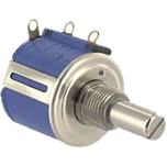
Example potentiometer
Example potentiometer
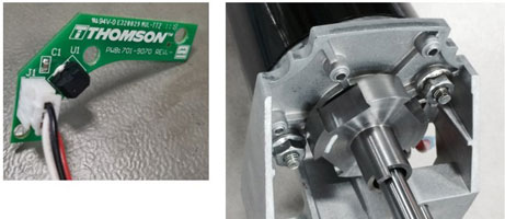
Encoder
An encoder provides a pulse output as the actuator moves. The pulse
output is usually for use by a control system such as a PLC. The
control system can use the output to determine relative position. Being a
relative position device, there is a need to “home” the system on
initial setup and any time the control system loses track of the pulses
(power outage etc.).
The image blow shows an example encoder. On the left is
an example of the sensor used inside a Thomson actuator. On the right is
an example of the trigger wheel used to trigger the sensor.
An encoder example
An encoder example
CAN bus
CAN bus provides data about the actuator digitally using CAN bus. Position feedback and operational parameters are transmitted on the CAN bus. This can simplify wiring.
CAN bus controlled system
In a CAN bus controlled system:- Power is distributed to each device. (red lines)
- Control system communications directly with actuators. Position feedback and operational parameters transmitted on the CAN bus. (blue lines)
CAN bus controlled system
In a CAN bus controlled system:- Power is distributed to each device. (red lines)
- Control system communications directly with actuators. Position feedback and operational parameters transmitted on the CAN bus. (blue lines)
Traditional system
In a traditional system:
- Power is distributed to each device (red lines)
- Control system communicates with each control box separately. (control box orange, communication lines yellow)
- Feedback from actuator requires additional wiring for each feedback device. i.e. potentiometer or limit switches (Green lines)