Thomson Linear Motion Optmized

Linear Actuators - Holding Brake
Design and Theory
As a general rule Industrial Linear Actuators are designed not to backdrive. Backdrive is when the load of a screw, actuator, or system is able to operate the unit in reverse when unpowered.
Backdriving on Industrial Linear Actuators can be prevented through various means. Some actuators are designed with self-locking lead screws. Actuators using ball screws incorporate holding brakes. The most common holding brake used is the wrap spring brake.
Backdriving on Industrial Linear Actuators can be prevented through various means. Some actuators are designed with self-locking lead screws. Actuators using ball screws incorporate holding brakes. The most common holding brake used is the wrap spring brake.

How backdriving is prevented
To learn how the wrap spring brake works read on, otherwise proceed to the next topic. (link)
How a wrap spring brake works
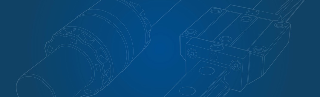
The main component of an actuator wrap spring brake is a wrap spring
clutch. A basic wrap spring clutch consists of two hubs and a wrap
spring. The wrap spring has an inside diameter that is slightly
smaller than the outside diameter of the two hubs. When assembled the
spring is forced over the two hubs.

A basic wrap spring design
A basic wrap spring design
Rotating either hub in the direction to uncoil or unwrap the wrap spring allows the hub to freewheel.
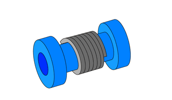
Motion unwrapping the spring allows for freewheeling
Motion unwrapping the spring allows for freewheeling
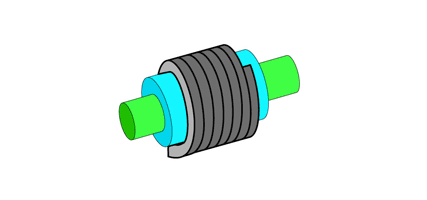
Rotation of the hub in the direction that coils the spring tighter causes the spring to wrap tightly onto the hubs positively engaging them. The greater the force of the rotation, the more tightly the spring grips the hubs.

Motion wrapping or tightening the spring causes engagement
Motion wrapping or tightening the spring causes engagement
If one of the hubs is held stationary this assembly could make a brake.
However it would only brake in one direction and freewheel in the
other. To brake in both directions, like in an actuator wrap spring brake, more components are needed.
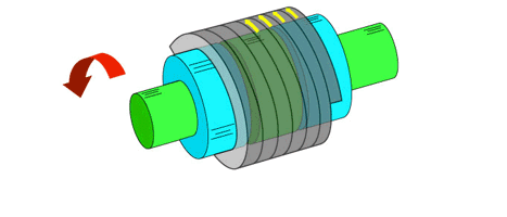
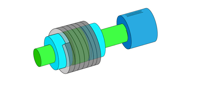
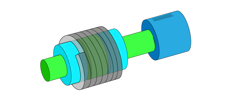
Actuators wrap spring brake
The actuators wrap spring brake is essentially 2 wrap spring clutches. The clutches share one common input hub that is at the center and 2 output hubs on each side. The input hub is attached to the screw shaft that is driven by the motor which causes the actuator to extend or retract (colored green in the animation).
Actuator brake exploded view (simplified)
Actuator brake exploded view (simplified)
Rotating the shaft and input hub assembly (green) clockwise the wrap spring wraps tighter on the input hub and left output hub which locks them together. The wrap spring unwraps on the right hub which allows it to slip.
Actuator brake rotated clockwise
Actuator brake rotated clockwise
Rotating the shaft and input hub assembly (green) counter clockwise causes the
input hub and right output hub to lock together. The left output hub is allowed to slip.
Actuator brake rotating counter clockwise
Actuator brake rotating counter clockwise
Motor driving the actuation
When the motor turns the screw and input hub assembly counter clockwise the actuator expands. When the actuator expands, the expanding force pushes the actuator against the left hub. As shown previously the left hub is the hub that is that slips in this direction. When the motor turns the screw clockwise the actuator retracts, the retracting forces pull the actuator against the right hub and the right hub is the hub that slips in this direction.
In the animation below:
- The extension tube with the nut contained in it are represented by the blue cylinder.
- The direction of the outside force, tension or compression, and the opposite force against the hub are shown by the orange arrows.
- the yellow arrows represent the forces that lock the hubs and spring together from the screw and input hub assembly rotating.
Actuator wrap spring brake expanding and contracting
Actuator wrap spring brake expanding and contracting
Holding a load
To make this assembly work as a brake, friction material is added to the ends of the outer hubs. When the load tries to compress the actuator the left output hub is pressed against the friction material braking the left hub. Similarly when a load pulls the actuator in tension the right
output hub is pressed against the friction material braking the right hub.
At the same time the compression or tension load applied to the actuator creates a
tendency for the screw to backdrive or rotate. This attempt to rotate will lock the screw shaft and input hub assembly to one of the output hubs. When the load tries to compress the actuator the wrap spring will lock the input hub to the left output hub. When a load pulls the actuator in tension the wrap spring will lock the input hub to the right output hub.
In the image below:
- The direction the screw would try to back drive is shown by the red arrows.
- The hubs and spring locked together from the screw and input hub assembly trying to back drive are shown by the yellow arrows.

Left: braking under compression. Right: Braking under tension
Left: braking under compression. Right: Braking under tension
Notice that the input hub assembly is locked to
the output hub that is being forced against the friction material braking
it from
turning. This happens in both the compression and tension scenario keeping the
screw and input hub assembly from turning. With the assembly restrained from turning the extension tube holds in position.
Helping loads
A helping load is a load that is in the same direction the actuator is moving. A compression load while the motor is trying to retract the actuator or a tension load while the motor is trying to expand the actuator.
This scenario is the same as the motor driving the actuator with one difference. The hub that is forced against the friction surface will be the opposite output hub. This means the rotating hub will be rotating against the friction material (shown as pink in the animation). In this situation the motor will power through the friction and expand or contract the actuator. However, this scenario does cause some wear on the friction material.
Actuator expanding and contracting with helping load