Thomson Linear Motion Optmized


Ball Screws - inspection
Installation Instructions
This document describes how to inspect a ball screw assembly.
See below for required tools and setup for inspecting and measuring the ball screw assembly.
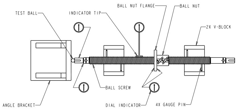
Figure 1
Figure 1
All tests should have the ball screw assembly located in the test fixtures as shown in Figure above.
Place the bearing ball at the end of the screw, between a right angle bracket and the ball screw. (NOTE: The right angle bracket must be clamped down or positioned against secure object to prevent movement.)
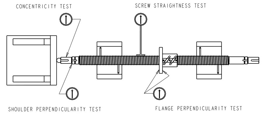
a. Shoulder Perpendicularity Test
Place the dial indicator on the shoulder of the screw (See figure above) and rotate the ball screw so that the pins rotate back and forth on the V-block and observe the dial indicator. Record the greatest deviation as indicated by the dial movement.
b. Concentricity Test
Place the dial indicator on an end journal (See figure above) and rotate the ball screw. Record the total indicator reading (TIR). Reposition the dial indicator as necessary to measure deviation across the entire length of the screw journal and record the greatest deviation indicated by the dial movement.
c. Flange Perpendicularity
Place the dial indicator on each of the flange mounting surfaces (See figure above) and rotate the ball screw. Record the greatest deviation as indicated by the dial movement.
d. Straightness Test
Install the flat tip assembly to the dial indicator (See figure above) and position on the screw at the far left of the assembly. Rotate the ball screw and record the greatest deviation as indicated by the dial movement. Repeat this measurement at the center and far right of the screw.
Compare recorded results from all tests to the standard tolerances shown in the figure above.