

By Anders Karlsson and Travis Gilmer
Product Line Specialists, Industrial Linear Actuators
Thomson Industries, Inc.
www.thomsonlinear.com thomson@thomsonlinear.com
Manufacturers of agricultural, construction and other mobile off-highway (MOH) equipment are increasingly deploying electromechanical actuators over hydraulic actuators, primarily for their simplicity and environmental benefits. But now, as electromechanical actuators become more intelligent through support of the Controller Area Network (CAN) bus networking standard, equipment designers have even more reasons to choose these solutions. Support for the CAN standard enables onboard intelligence that can lead to dramatic improvements in performance and maintenance.
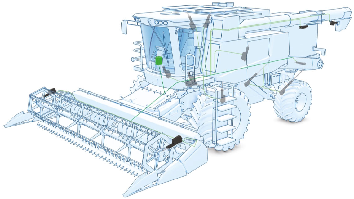
Figure 1: Although the CAN protocol continues to grow in importance amongst industrial automation
and mobile machines, there is no doubt that the mobile off-highway market is where CAN bus version
J1939 will be predominantly used.
Environmental protection plus
Hydraulic cylinders are often applied in high-force motion control in mobile equipment, but the fact that
they require fluids that are toxic to people and the environment is of increasing concern. Chemicals
such as butane, esters and organophosphates can be released from damaged equipment and during normal operations or routine maintenance. The production, transport and handling of materials prior to application also contribute risk. These concerns have opened the door for alternative solutions.
Electromechanical actuators have emerged as an environmentally friendly alternative to hydraulic actuation. Their performance in heavy duty applications is comparable to that of hydraulic actuators, and with added support for the CAN bus protocol, this new generation of smart electromechanical actuators offers significantly enhanced position control, monitoring and overall lifecycle cost savings.
Smart architecture
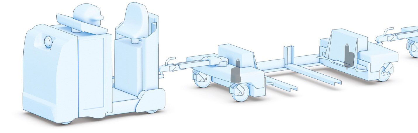
Figure 2: The Thomson Electrak HD, with its built-in J1939 CAN bus capabilities, makes it easy to build intelligent logistic systems such as the material handling train shown here.
The CAN protocol is an ISO standard (ISO 11898) for serial data communication. It was originally developed for automotive applications but is now also used in industrial automation and mobile machines. The MOH market predominantly uses CAN bus version J1939, which has been advanced to address the specific needs of agriculture, construction and other MOH applications.
J1939 is a high-level communications protocol that provides a standard messaging structure for communications among network nodes under control of an electronic control unit (ECU). Every message on an actuator module representing a J1939 bus node has a standard identifier indicating message priority, data and control source. This enables plug and play interchanges of supporting devices that share the same network and comply with the messaging structure.
Figure 3 shows a typical CAN bus network, illustrating four actuators with built-in CAN bus-compliant intelligence. Each actuator has two wires, one that connects to an external power source and the other that communicates with the control source. The green box represents sensors or other components that could also be wired to the power source and the communications network, without external relays. The orange line represents the two-wire bus that transmits the low voltage of power needed for the system, and the blue line represents the two wires that are used for information exchange. This represents a dramatic improvement over conventional vehicle networks in at least the following ways:
- Power is distributed across common wiring, eliminating the need for separate wiring between each device and the power source
- Switching is embedded in the actuator electronics, eliminating the need for cumbersome external switching and connectors, etc. All commands are executed in the actuator.
- Information flows to an electronic control unit (ECU) from each device via the network bus, eliminating the need for independent connections between the devices and the ECU
- Other equipment that might be integrated into the system connects with the network in the same way, eliminating the need for separate wiring, controls and additional configuration
- A typical CAN network supports up to 256 nodes, including multiple actuators or other devices on each node, something that would be all but impossible with a conventional network
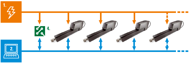
Figure 3: Typical CAN bus network, illustrating four actuators with built-in CAN bus-compliant intelligence.
The result is an efficient, compact solution that provides unprecedented monitoring and advanced control capability. With onboard J1939 compatibility, actuators speak the same language as the ECU, allowing communication across a shared bus. It is dramatically different from conventional electronic architectures since they require a standalone ECU for each operation. Additionally, this also enables more complex control strategies, which may include deploying the same actuator in multiple applications.
Embedded position control
Position control with an embedded J1939-compliant actuator is superior to that of a hydraulic actuator because it provides an absolute reading of position. A 14-bit signal informs the user of the actual actuator stroke position between 0.0 mm and a fully extended stroke, the accuracy of which depends on the stroke length and mechanical tolerances of a given model. Accuracy of the signal itself, for example, could be 0.1 mm/bit, which could contribute to overall system positional accuracy of +/- 0.5 mm or better depending on tolerances in the gearing, ball nut and screw assembly.
Achieving that kind of positional accuracy on a hydraulic system is expensive and hard to maintain. Instead of receiving a consistent electronic signal, monitoring the position of hydraulic actuators requires measuring the amount of fluid that is being pumped through the lines and then using externally mounted encoders and limit switches to signal a control box when the desired points have been reached. This requires fluid to be in motion throughout the system at all times, and when pumping stops, system creep affects the position and requires recalibration. It also renders hydraulic actuation much less effective for heavy duty applications requiring consistent, high-precision position control over longer periods. CAN bus systems, on the other hand, use encoders, limit switches and potentiometers to control position, and these are designed into the system electronics to enable absolute position determination.
One key benefit of absolute position control is that it enables consistent, reliable position memory. Because many MOH machines are run by the season and might sit idle for eight or nine months, it is sometimes valuable to disconnect the battery to prevent it from draining. Without absolute position capability set at the factory, the user will have to recalibrate once they reconnect the battery.
Low-level power switching
Low-level power switching is standard with the J1939 protocol, allowing operators to program the actuator to extend, retract or stop smoothly using low-level electronic signals rather than a higher-energy electrical current. This improves safety by reducing the hazard of electrical shock and simplifying design by allowing lower-rated control components. Soft start capability also allows use of lower-rated power supplies and puts less stress on batteries and charging systems in vehicles.
Low-level power switching also enables controlling standard inrush to be to up to three times the full load amperage for up to 150 milliseconds. This would enable direct programmable logic controller (PLC) connections, eliminating the need for expensive relays and the related installation costs. It also could include a sleep mode when the actuator is idle, which extends battery by reducing energy consumption and battery drain.
Dynamic braking control is yet another benefit of low-level power switching. Once the power is cut to an actuator, it could take between 5 and 10 mm to coast to a full stop, depending on how the actuator is mounted. Electronic actuators enable dynamic braking functionality, which can reduce that coast to about 0.5 mm by electronically forcing a short between motor leads inside the actuator. This improves repeatability and positioning capability.
Programming capability
Such advanced position control and switching enable programming of the drive to perform with an infinite number of movement profiles and custom motion strategies. For example, users can program the actuator to seek forward a few millimeters or make a small set of movements back and forth to hunt down a desired position. And because the system knows what it is supposed to do and monitors performance in real time, it can flag potential variances and trigger advanced algorithms to manage further alarms, corrections or shutdown.
With the J1939, system developers will have much greater flexibility to program the sensors and internal electronics to synchronize operations among multiple actuators. For example, they can program units to vary in speed depending on load or change speed to compensate if units speed up or slow down.
Electromechanical actuators without J1939 support can provide absolute position readings, but they typically require significant power, heavier wiring, relays and other space-consuming and vulnerability prone wiring. J1939 enables all of this to be embedded directly into the actuator and managed by embedded, low-level switching connected to the 2-wire CAN bus communications network and two power wires. This not only simplifies wiring in the vehicle, it brings all of those previous external electronics into the product – and warranty – of the actuator vendor.
Diagnostics and maintenance
In addition to returning real-time position data to the user J1939-enabled actuators are constantly returning results of ongoing monitoring of temperature, current, speed, voltage and other variables, which enables advanced diagnostics and error handling. Feedback can arrive as quickly as ten times per second as the actuator constantly tests itself. If it detects a problem, such as surpassing a temperature threshold, the actuator finishes its programmed move – either fully retracted or extended – stops and sends an error flag to the computer, all in fractions of a second. Following are some of the variables that can now be monitored with unprecedented efficiency:
Current. Current monitoring is a critical safety feature that shuts down the actuator on overload and eliminates the need for the traditional noisy mechanical clutch.
Voltage. Continuous monitoring of voltage protects the actuator by preventing motion if it detects it operating in an environment outside of the acceptable range.
Temperature. Internal temperature is monitored and, if outside the acceptable temperature range, the actuator is shut down after extending or retracting stroke. Built-in temperature compensation allows the actuator to push the rated load at lower temperatures without nuisance tripping.
Load. Trip points can be calibrated at assembly to assure repeatable overload trip points independent of component and assembly variations. This not only assures repeatable performance, but also relieves the user of having to recalibrate in the field.
All such functionality can now be embedded within the actuator, available instantly and, via the network, potentially sharable for assistance with external troubleshooting. Thomson smart actuators, for example, are a plug and play solution, easily swapped out in case of a problem. On the other hand, replacing a problematic hydraulic actuator could involve a service call from the manufacturer and hours or even days of disassembly, reassembly, system bleeding and testing-- time that would be better spent in production.
Moreover, system health monitoring can occur remotely. For example, an OEM support technician in Iowa can log in to a combine in North Dakota to diagnose a failed actuator by analyzing electronic message flags on temperature, position, current and input voltage.
Enriching the dialogue
In many ways, optimizing the performance of an actuator is a function of the dialogue quality between the users and the device. With J1939-compatible language combined with advanced embedded electronics, users have more flexibility in telling their actuator where and how fast they want it to move, and when they want it to stop, and they will get instant feedback as to whether it has behaved accordingly.
You can engage in this kind of dialogue with a non-J1939 electromechanical actuator, but it requires more external switches and wiring. You can also engage with a hydraulic actuator, but it is a far longer, much more complicated conversation. By utilizing a common, highly efficient language, the J1939 standard moves the discussion from how the communications will be managed to what exactly the user wants to accomplish. The end result is greater control and design flexibility, faster engineering, more efficient installation, and overall lower cost of ownership.