

Linear motion designers often choose round rails over square rails to reduce costs in low-stress applications or when requiring a high tolerance for misalignment. Whether these designers achieve the intended benefit depends on how carefully they select from among the many available round rail shafting options. Round rails will, for example, vary in physical form factors such as hardness, straightness, surface finish, roundness and cylindricity. They come in multiple grades of steel as well as aluminum, each of which might be coated with other materials. Numerous mounting and configuration considerations also impact costs.
savings in original shafting cost most often result in a net loss based on the data showing decreased life of the overall assembly. Therefore, a basic understanding of key round shaft factors and how they influence precision and durability will be invaluable in helping you select the ideal shaft for your designs.
Understanding shaft physical form factors
Key shaft features that interact with one another to impact precision and durability include hardness, straightness, surface finish, roundness and cylindricity.
Hardness
Shaft hardness affects the dynamic load rating of the bearing. Harder shaft surfaces better resist permanent deformation under single-point loading of bearing balls, thus maximizing the life of both the Linear Ball Bushing® Bearing and the rail itself. A common process for hardening linear shafts is “case hardening,” in which the manufacturer adds a hard, wear-resistant outer layer by heat treating the shaft, while keeping the core soft.
Figure 1 shows how the bearing load correction factor and consequently, life expectancy, must be adjusted downward as hardness drops below 60 HRC.
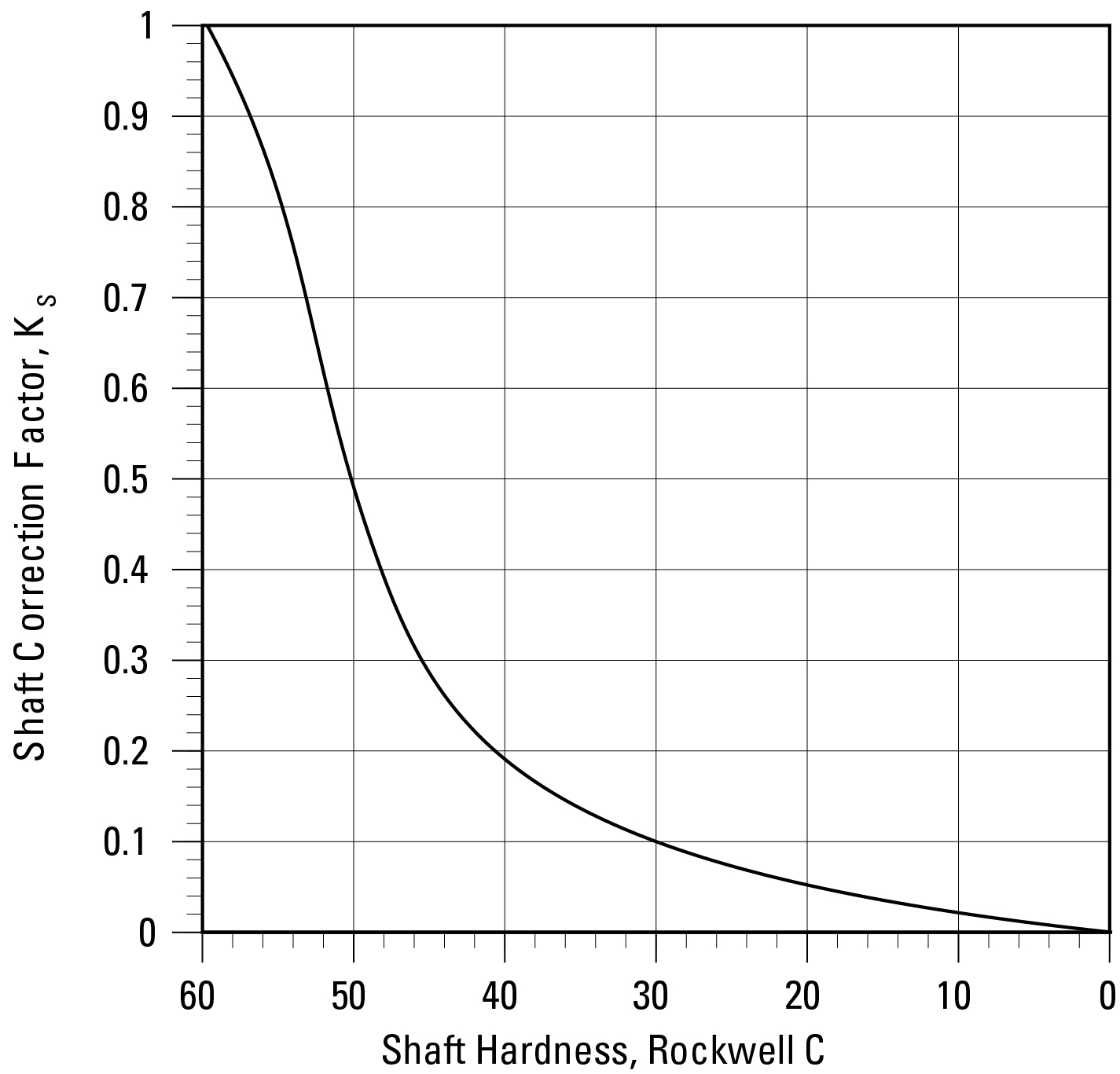
Figure 1: Shaft correction factor reduces dramatically as HRC hardness drops below 60. (Image courtesy of Thomson Industries, Inc.)
The depth of the case hardness is another factor in determining overall life. Higher loads subject the shaft to deeper bearing ball penetration and higher stress concentration. High deformation resistance in these situations then requires deep and uniform case hardness and must be engineered to Linear Ball Bushing Bearing size and load expectations. Best-in-class Thomson 60 Case® carbon steel shafts, for example, might have case hardness values ranging from 63-67 HRC and case depth of values of up to 0.1” depending on shaft size. Special deep case (DC) options are available with case depths up to 0.25”, helping to achieve longer life.
Straightness
Straightness is perhaps the most vital parameter for positioning accuracy in a Linear Ball Bushing Bearing system. The straighter the shaft, the higher the precision. Lack of straightness can cause binding, noise generation, premature wear and failure of the ball bearings.
Best-in-class linear shafts are straight to within 0.001” per foot cumulative (0.002” TIR) and can accommodate special straightness requirements of 0.0005” per foot cumulative (0.001” TIR) for critical, high-accuracy applications.
To assess proper straightness, place the shaft on two or more V-blocks as indicated in Figure 2. Rotating the shaft 360°, use a dial indicator to record the minimum and maximum readouts along the length of the shaft during rotation. The difference between the minimum and maximum values is known as total indicator runout or TIR.
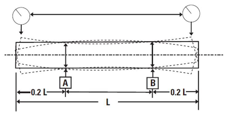
Figure 2: Shaft straightness is calculated as the difference between the minimum and maximum readout values along the length of a rotating shaft. (Image courtesy of Thomson Industries, Inc.)
Surface finish
Surface finish (or RA for roughness average) is a measure of how smooth or rough the surface of the shaft. It represents the average height of the microscopic peaks and valleys along the length of the surface of the shaft. Superfinishing levels more of the peaks along the shaft’s surface to produce a series of plateaus, as shown in Figure 3, thus increasing the percentage of shaft surface area that is available to the ball bearing. This increases the amount of shaft surface on which the linear ball bearing can ride, distributing the load more uniformly along a larger area and thus maximizing the life of all components. Surface finish is a key factor affecting Linear Ball Bushing Bearing travel life, load levels, frictional resistance and smoothness of travel. The smoother the ride, the longer the life.
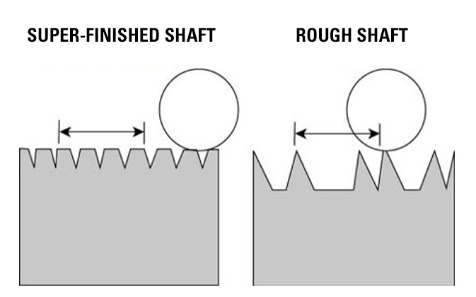
Figure 3. The super-finished shaft on the left results in smoother movement by increasing the percentage of shaft surface area on which the Linear Ball Bushing Bearings can ride. (Image courtesy of Thomson Industries, Inc.)
Roundness
Roundness is the tolerance that controls how closely a shaft cross-section matches a mathematically perfect circle. The rounder the shaft, the more uniform the distribution of bearing loads and the longer the bearing travel life. Variations in a shaft’s radii can cause rapid alternate loading as the bearing rides along the shaft. Shafts that are out of round by even 0.0001" create preloading on some of the ball tracks, causing uneven wear, premature failure and shortening bearing life by as much as 50%.
High precision applications require a roundness tolerance of 0.000080”, which manufacturers achieve by a process known as centerless grinding, as shown in Figure 4.
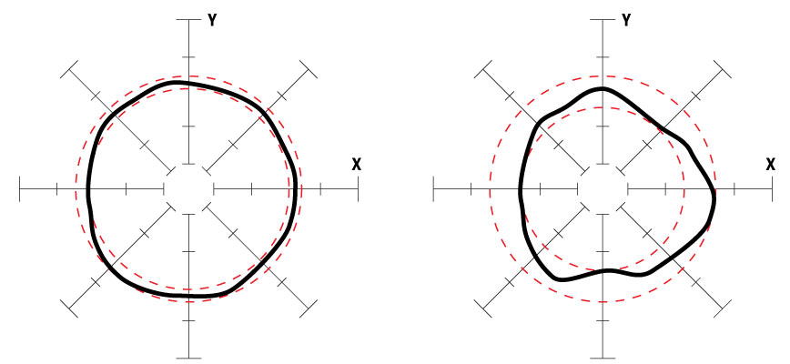
Figure 4. These two plots of shafts illustrate different roundness tolerances. On the left, a proprietary centerless grinding process produces shafts with a roundness tolerance of 0.000080” to ensure uniform distribution of bearing loads for maximized bearing travel life. Rounder = longer bearing life. (Image courtesy of Thomson Industries, Inc.)
Cylindricity
Cylindricity is a measure of the degree of conformance of the shaft (or linear race of the Linear Ball Bushing Bearing) outside surface to a true cylinder. High cylindricity ensures consistency of roundness and straightness along the entire length of the shaft – not just in a particular location. This ensures uniform load distribution of bearing loads, maximizing load capacity and travel life in the linear guidance system. High cylindricity equals higher precision, higher load capacity and longer life.
Taper is a cylindricity measure of the change in diameter any place along the length of the shaft. It subjects the bearing to shock and preload conditions and can cause one bearing to be loaded higher than another. Going in and out of a preloaded condition causes premature wear, which drastically reduces overall bearing life expectancy. For linear motion applications, look for shafts with a maximum taper of half the diameter tolerance over the length of the shaft. This ensures uniform distribution of bearing loads and maximizes bearing travel life.
Material matters
The most common materials used in shafts are carbon steel, 52100 tubular carbon steel, 440C stainless steel, 300 series stainless steel, and aluminum. Each has unique capabilities, and it is critical to match each to the application.
Carbon steel
Carbon steel (Figure 5) is the most commonly applied shafting material for linear motion applications, representing more than 85% of all shafting sold. It is the least expensive and, when processed, results in the hardest and deepest case, as well as high yield and tensile strength. It is often used in general industrial applications, including factory automation, material handling, woodworking, packaging and semiconductors. It is highly versatile and has multiple plating options that add corrosion and wear resistance.
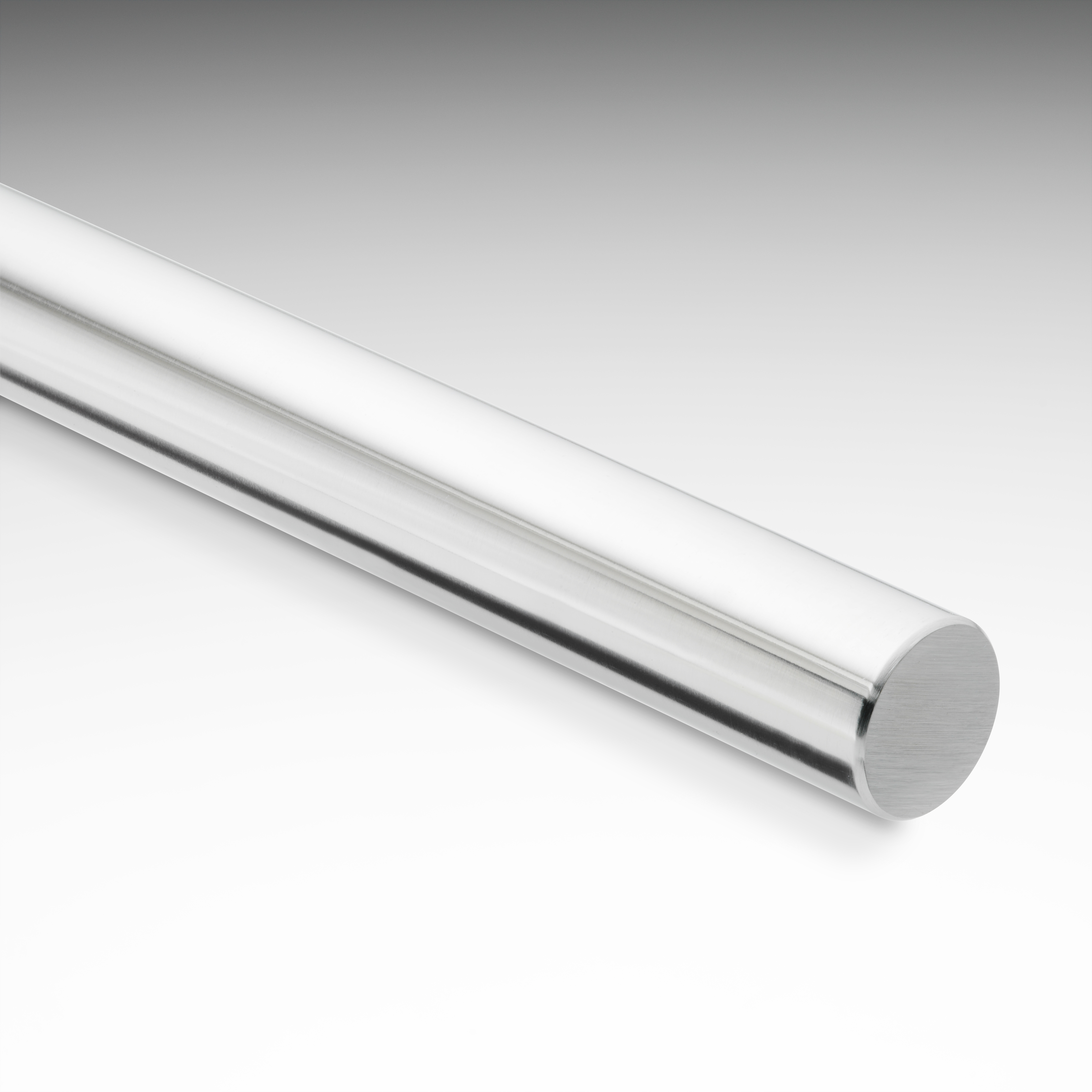
Figure 5: Carbon steel shafting is the most commonly used for linear motion applications. (Image courtesy of Thomson Industries, Inc.)
The most common grades of carbon steel available in North America include 1050, 1055, 1060 and 1566. These follow the AISI/SAE numbering systems, in which the first digit indicates the type of steel, the second digit is for special alloys that may be added, and the last two digits represent the percentage of carbon in the material. The percentage of carbon is the biggest differentiator among shafting materials and determines the maximum hardness achievable with the material.
Other common alloy elements found in carbon steel include sulfur, phosphorous and manganese. The amounts of sulfur and phosphorous in carbon steel should be minimized to avoid brittleness and crack sensitivity. Increasing manganese improves the hardenability and tensile strength of the steel but to a lesser extent than carbon. During the heat treat process, manganese helps stabilize the quenching process at a slower rate, minimizing the rate at which defects form. This determines how the given microstructure will respond in uniformity and consistency of both case hardness and case depth.
For maximum performance in most linear applications that use Linear Ball Bushing Bearings, look for carbon steel material with a carbon content greater than 0.60% and manganese content greater than 0.05%, which allows for the hardest and most uniform Rockwell hardness values and case depths.
Carbon steel is prone to corrosion and requires lubrication to prevent rust or oxidation from forming. For this reason, plain carbon steel is not typically used in corrosive environments. When corrosion resistance is required, an optional plating, such as chrome, can be applied.
440C stainless steel
440C stainless steel is a popular material for industrial automation because it allows a level of corrosion resistance while still having the ability to be hardened, which allows it to be used with Linear Ball Bushing Bearings. As shown in Figure 1, 440C’s typical hardness range of 50 to 55 HRC would reduce shaft life by 20 to 50% compared to carbon steel. A chrome-plated carbon steel shaft will offer better life if corrosion resistance is needed.
300 series stainless steel
Designers needing non-magnetic materials often choose 300 series, but this is not suitable for use with Linear Ball Bushing Bearings because they do not offer any hardenability. 303 stainless does have a high sulfur content, which gives high machineability but reduces corrosion resistance and toughness. There is a 304 grade which does have exceptional corrosion resistance to chemical and atmospheric conditions, but it is less machinable than 303 and 316 grade. The 316 offers even less machineability than either 303 and 304 series but provides more corrosion resistance than both.
52100 tubular carbon steel
Motion system designers often choose 52100 tubular carbon steel when they want a lighter weight shaft or prefer to route fluids, lines or other components through the shaft. (Figure 6) The tubular design reduces weight by 29 to 56%. It is bearing-grade chromium steel with a carbon content that allows for good hardenability with hardness values in the range of 58 to 62 HRC.
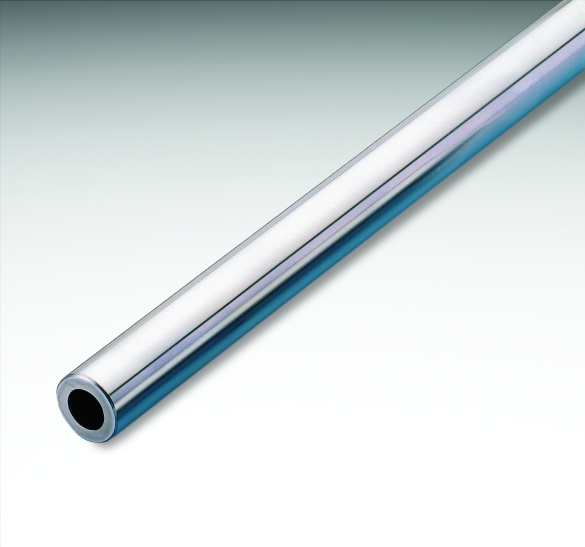
Figure 6: Lighter weight and the ability to route fluids, lines or other components through the shaft make tubular carbon steel a popular option. (Image courtesy of Thomson Industries, Inc.)
Aluminum
Aluminum shafting is usually offered with either a ceramic or hard-anodized coating. The coating hardness is nominal at the surface level only. The shaft underneath the coating is soft and would deform at high point loading of a Linear Ball Bushing Bearing so it is not suitable for use with them. The benefit, however, is a significant weight reduction compared to other shafting materials, while also offering good corrosion resistance.
When “soft” shafting is used, plain bushings that do not contain ball bearings are selected to prevent damage to the shaft, while still providing linear motion.
Plating extends life
The two most common plating options to reduce wear and increase corrosion resistance are hard chrome and Armoloy. Both are offered with a thickness near 0.0001”, which does not affect the shaft tolerance range once plated. Both offer increased hardness levels and long life, with Armoloy achieving a higher hardness level of 78 HRC compared to a range of 65 to 72 HRC for hard chrome. The main benefit of the Armoloy is the absolute adhesion of the plating to the base metal, which helps prevent chipping, cracking, flaking or peeling.
Mounting issues
Support rails offer continuous or intermittent shaft support to best resist deflection. They offer the ideal option for long-length assemblies where shafts can be segmented together via butt joints to give virtually unlimited travel length. Support rails are available in either T-shape, low support or block configurations. Standard T-shape aluminum rails are most common. (Figure 7) Bolts extending through the bottom of the rail hold the shaft in place, while the support rail itself bolts to the equipment from the top down.

Figure 7: Standard T-shaped aluminum support rails.
Low support rails are often made from a steel alloy that is designed for rigidity and offers 40% lower overall height for more compact installations. Low support rails can bolt from the top or bottom, providing installation flexibility.
Standard support blocks
When surface conditions or spans do not allow for continuous support, end supports can be used to mount round shafting. Support blocks are used to span gaps of 4 to 12 times the shaft diameter, but at such long lengths, there is risk of deflection. Unlike square rail, round rail can handle some degree of deflection and misalignment when coupled with the appropriate bearings. Selecting self-aligning bearings with up to ±1/2 degree of misalignment capability allows for continued smooth travel, where standard bearing designs would bind. Support blocks are commonly available for end or intermittent mounting or flanged for perpendicular mounting. (Figure 8)

Figure 8: Support blocks clamp to the ends of the shaft or intermittently to keep it in position. (Image courtesy of Thomson Industries, Inc.)
Configuration basics
How the shaft and bearing are configured will also impact accuracy and durability. These include the ratio of the stroke length to bearing length, the number of shafts used, the number of bearings used and the aspect ratio between the parallel shafts and bearings.
Special considerations for short stroke applications
In most applications, the shaft receives less stress than the bearing plate because motion is spread across a long distance and will outlive the bearing. But when the shaft stroke is less than twice the bearing length, the situation reverses. Higher stress cycles accumulate on the shaft rather than on the bearing plate, limiting its lifecycle.
Although the application will dictate the stroke parameters, the designer should include a short-stroke lifecycle correction factor when setting the dynamic load rating (D-rating) during design.
As shown in Figure 9, if the stroke is less than 1.5 times the bearing length, you must decrease load capacity by up to 42% of the normal system load. For example, if a 2-in.-long bearing operates with a 1-in. stroke, its load capacity should be multiplied by 0.60 (60%).
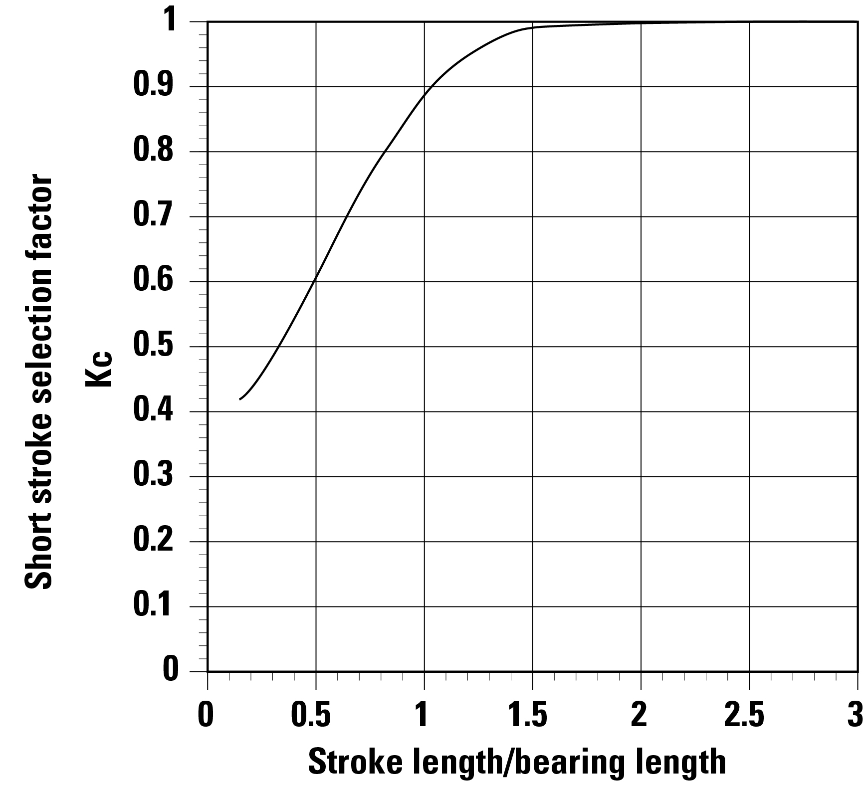
Figure 9. When the shaft stroke is less than twice the length of the bearing, designers must correct for the D-rating.
Two shafts are better than one
Two shafts are always necessary because a round bearing cannot account for moment loads. This does, however, make installation more difficult because parallelism between each shaft must be within 0.001” over the entire length of the system.
Two bearings per rail
Likewise, there should be two bearings per rail to achieve equal load. This also allows the designer to take advantage of a half-degree self-alignment feature that is available in certain round rail bearings. Installing more than two bearings would not be prudent, however, because equal load sharing and alignment would be difficult to achieve.
Healthy ratio of bearings to shafts
The maximum aspect ratio between the parallel shafts and related bearings should be 3:1. As shown in Figure 10, spreading the bearings on the shaft at 1/3 the distance between the parallel shafts is recommended.
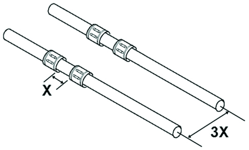
Figure 10: Spread between multiple bearings should be 1/3 the distance between parallel shafts.
Tool talk
Having an informed understanding of the factors that impact precision and durability will help designers make the optimal shafting choices for their applications. Knowing the characteristics of the production process, materials and configuration options will make it easier to sort through the advantages and limitations of available options. Increasingly, motion control vendors are providing sizing and selection tools that enable designers to easily enter specifications and receive recommendations immediately.
Designers using the Thomson Linear Motioneering® tool for round rail shaft sizing and selection, for example, enter application requirements such as orientation, positioning profile, load and dimensional information, and environmental conditions, and can instantly download CAD models and gather additional linear product information.
Thomson also offers an online tool that uses a simplified, application parameter-based selection process to quickly narrow searches for shafts. Users are provided a list of recommended shafts, and access to 3D models, upfront pricing and lead times, and can instantly purchase their optimal shaft solution.
For more information about Thomson Linear Motioneering tools for shaft selection, visit https://linearmotioneering-shafting.thomsonlinear.com/wfrmHome.aspx. The shaft selector tool can be found at https://www.thomsonlinear.com/en/products/shafting-products