

By Kyle Thompson,
Product Line Manager Systems Group
Thomson Industries, Inc.
Wood Dale, IL
There are many industrial applications requiring linear motion, and for most applications this is served by a conventional belt or screw drive system. Both have advantages and disadvantages and meet the needs of most applications well but issues start to arise when longer linear distances are required.
Belt systems are an obvious choice where long linear movements of over five meters are required. These relatively straightforward systems use pulley drives to create tension along the belt, and they can be brought quickly up to high speeds of around 10 meters/second. However, although these systems can be designed with up to 12 meters stroke, as they reach longer lengths, issues start to arise with belts sagging as tension cannot be maintained across the whole length of the system. There is also inherently a lot of give in the system from the rubber or plastic belts themselves. This flexibility across the length of the system can cause vibration or springing which creates a whipping effect for the carriage that affects precision within the system. If a specific process cannot handle this, a screw system offers a solution with a fixed mechanical element ensuring complete control at all times with exact stopping and positioning. Safety may also be a consideration when choosing a belt drive system, because of the possibility of a belt breaking. Such a fault would be uncontrolled and, in vertical applications, the load could fall and damage machinery or even personnel. Even upon failure, a screw drive system would stop the load from falling and ensure safety.
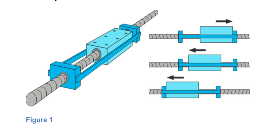
Historically, the issue with a screw drive system is the difficulty in reaching longer stroke lengths. They can commonly be provided in lengths of up to 5.5 or 6m using pairs of bearing blocks to support the screw and stop any whipping effect at higher rotation speeds around 3000 rpm. Even at lower speeds, longer screws need support against bending caused by their own weight. The extent of this support is depended upon the size of the unit, the load, speed and lead of the screw. This bearing block support system traditionally consists of pairs of blocks, typically 100 – 500 mm apart, connected together with a rod or wire and the pair move together along the linear motion system as shown in Figure 1. The figure also shows how the carriage will contact one of the screw support edges and cause it to move and, because these screws supports are connected by a wire, cause the entire assembly to move.
When a system requires a longer stroke, more bearing block pairs may be added to support the screw at regular divisions along its length. Having up to three or maybe even four pairs working together can be practical, but connecting the rods or wires between the blocks beyond this number within the limited footprint available starts to become difficult without fouling with other critical components. The first challenge to achieving a longer stroke, therefore, is to create a system which can offer more support points for the longer screw. One solution is to do away with the ‘connected’ system for the blocks and, instead, use a system where the blocks can collapse into each other and separate out when required, as shown in Figure 2. Once the blocks reach their position they stay there to guide and support the screw. In such a system 10, 12 or even 13 support points can be realised with bearing block pairs to produce ball screw units with up to 11 meters of stroke length.. The distance between the screw supports varies according to the size of the unit but is typically between 0.5 and 1 meter.
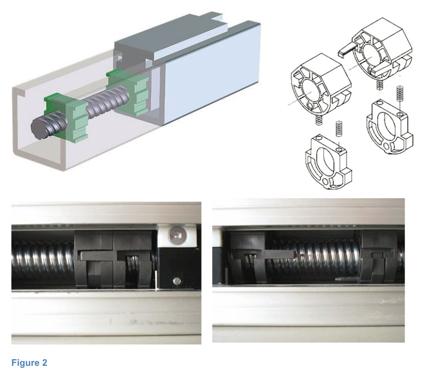
The screw supports are made of plastic, are an integral part of the offering and are designed to ‘nest’ within one another. The supports reside in machined pockets within the extrusion base and, with the exception of the end screw support, when nested they are locked together. As the carriage moves along the unit, the screw support will be picked up by the arms of an already nested screw support and be taken in the direction of motion. After the carriage passes over that extrusion pocket, a screw support from the other side of the carriage is dropped off. This is accomplished as the outer screw support within a nest is always unlocked. A spring mechanism is located within the screw support. When unlocked, the spring mechanism pushes on the extrusion base until it comes to the next available extrusion pocket. Once the support hits a pocket and is dropped off, another screw support is freed to stop at the next extrusion pocket.
This system of support for the ball or lead screws can enable long distances without bending or whipping while maintaining rotation speed. To go beyond six metres in length the next challenge is to create a longer screw. However, due to restraints in the raw material available, screws are only normally produced up to six metres in length. So how can a stroke length of over ten metes be achieved? The answer lies in attaching two screws together and employing some very precise manufacturing technique.
Lead and ball screws are manufactured on a rolling line and each piece part may be produced with a slightly different deviation. To join two parts together, therefore, differences in lead deviation need to be overcome. For two screws to be successfully joined the highest precision ball screws with the smallest possible deviation must be used. The ball screws need to be precisely machined; ensuring heat does not enter the part and cause changes to diameter and lead geometry as one hundredth or even one thousandth of a millimetre change can create problems for the final system. Once the machining process delivers the accuracy required, the screws are married together using a tap and hole with minimal deviation between the two leads. This assures that there is no difference in lead deviation for the extended length, joined lead screw from that of a single, solid piece shorter ball screw. The parts are finally secured using high strength glue as any thermal or welding join would again alter the geometry and create problems
Creating a solution with the collapsible support block system and precision manufactured long screw length means stroke lengths of 10.8 metres and over are achievable. The length of screw produced is only limited by the desire to join two screws together, assuring accuracy and performance are maintained, and the logistical practicalities of shipping such a product. A system with a stroke length of two to three metres would have a maximum speed of around 3/4000 rpm. Normally with a longer system the rotational speed would have to be lowered considerably to avoid whipping, but Thomson has engineered a solution using these additional supports to maintain stroke lengths over 10 metres at 3/4000 rpm. This leaves the user with the benefits of the stiffness of a screw system, long stoke length and high transportation speeds.
Where do you need a long screw drive system?
Screw drive systems with long stroke lengths are used in a wide range of industries to provide precise linear motion control, for example in welding systems where very accurate positioning of a welding nozzle is required. In applications where high quality materials are being used, such as titanium, the welding is carried out in a vacuum to avoid oxidisation of the metal. Parts such as long tubes in these applications require long screws to give the linear reach required.
Several applications within the automotive production lines, such as moving robot-welding arms between stations, also require long stroke linear motion. Although speed may not be a critical factor for transporting robot arms, long length and very accurate positioning are required. Within the automotive industry and several other market areas there are also many applications which require the transfer of material between assembly stations. Often these must deliver exact positioning for components moved between pick and place stations, and the screw drive again provides a good solution.
The manufacture of optical cable is a high-speed application which cannot be stopped without jeopardizing the quality of the fibres being produced. The cables are spooled onto large reels and, when one reel is full, it needs to be replaced as quickly as possible to minimise the loss of product in this continuous process. Precision and speed are vital to the process efficiency and long screw drives can offer both in this application, along with the capability of handling the heavy load of the reels.
Any application requiring the movement of heavy equipment in the vertical plane benefits from the rigidity and failsafe functionality of a linear screw. In the aircraft industry, for example, high precision cameras used for quality assurance are moved up and down and the screws carry the heavy weight securely and precisely. In such applications, special ball guide systems with large diameter balls are used to take up the dynamic load moment.
Improvements to existing systems
Many existing applications work with long screw systems up to five or six metres where the screw is left completely open. There are two common issues with such systems:
- The system cannot operate at the desired speed.
- The system is difficult to maintain as the open screw attracts dust and debris, requiring regular cleaning to avoid premature failure of the ball nut.
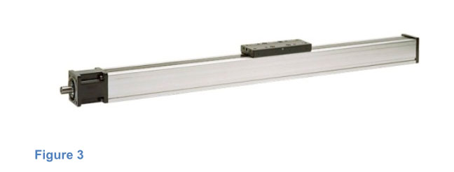
In such applications, the additional supports provided by the stacking bearing block configuration mean the screw can be operated at a much higher speed. Cleaning and reliability issues can be resolved using a covered, sealed system which protects the screw and offers significant reductions in maintenance requirements. The enclosed screw, as shown in Figure 3, is protected from ingress of dust and debris and, without regular cleaning, can maintain optimum performance and reliability. In such a system the carriage can be equipped with drilled channels and connected with a grease nipple attached to pre-drilled holes in the carriage. This enables lubrication from a single point with the grease entering both the ball-guided bearings and ball screw without having to open the casing. Most other types of linear unit require these parts to be greased separately but the Thomson design ensures comprehensive maintenance is quickly achieved. As the unit never has to be opened, very limited amounts of dust or water can penetrate the system and the system is protected even in the dirtiest environments.
Summary
As with any process, specific application requirements dictate which technology offers the best solution. Linear motion systems using screws offer the ability to handle larger loads than non-rigid, polymer belt systems. The screws are robust pieces produced from stainless steel and, if manufactured to the correct tolerance class, can be used to reach stroke lengths well in excess of 10 metres. Thomson’s innovative, collapsible bearing block support system ensures support of the screw length to avoid whipping and bending while enabling the system to operate at the higher speeds usually only associated with shorter length systems. Long stroke linear screw drive systems offer precise positioning with fast, safe operation. When operating in the sealed enclosure, they are further designed for continued reliable use and minimum maintenance requirements, even in harsh environments.