

Depending on your application, high speed is sometimes considered “the name of the game.” And when it comes to using profile or round rail as part of a linear motion solution, many variables for each can affect your application’s speed. To optimize these rails for your desired speed requirements, it is vital for engineers to become familiar with the design factors that impact the speed of each component.
Speed factors for profile rail
Profile rail, which is also known as square rail, has three main components: 1) a profile rail, or inner race, which guides the load to the desired position; 2) a bearing carriage, or outer race, which attaches to the load and the rolling elements that enable smooth motion across the rail; and 3) end caps, which are mounted on both sides of the bearing carriage, keeping the rolling elements contained and circulating (Figure 1).
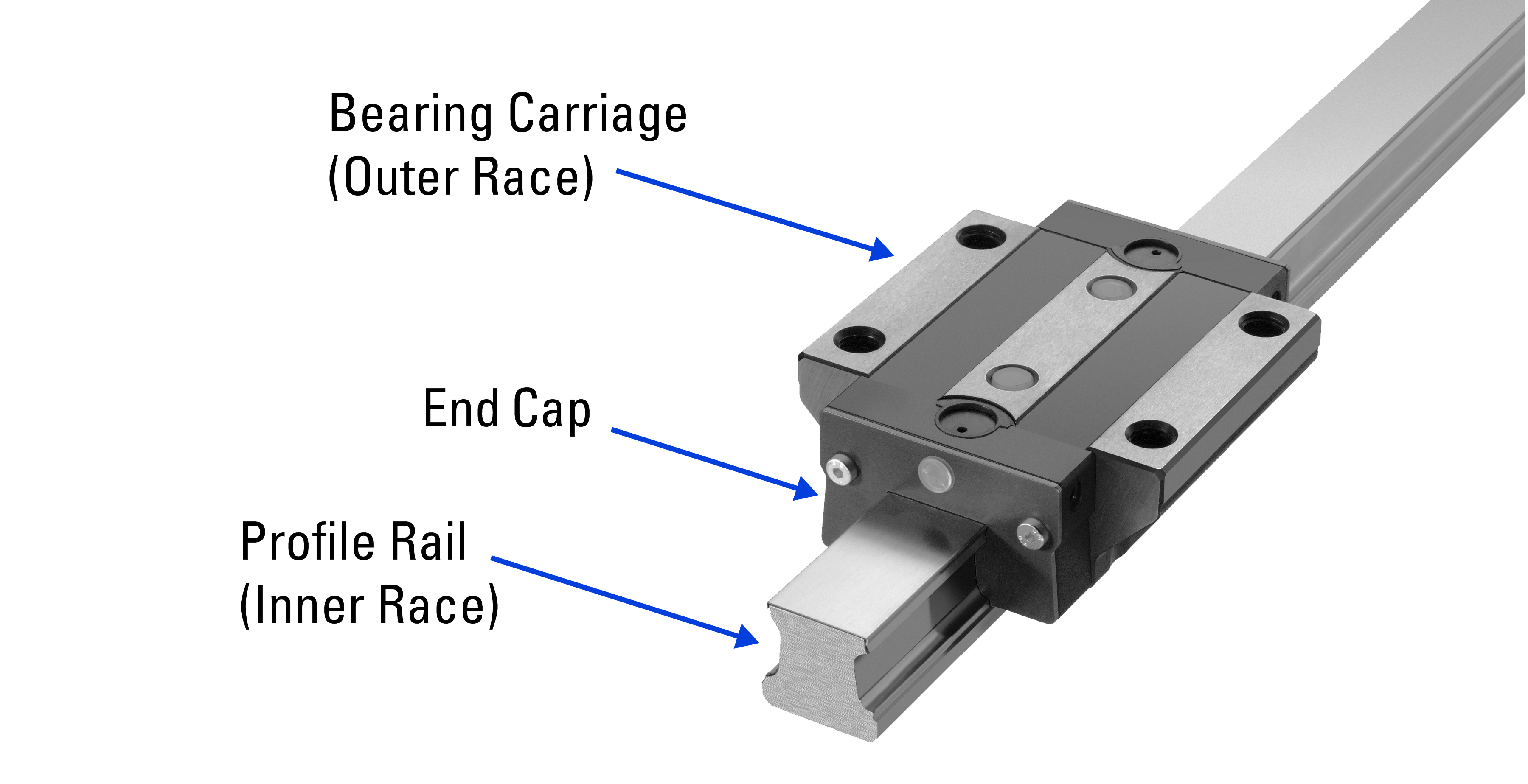
Figure 1. Profile rail systems include a square (profile) guide rail, bearing carriage and end caps.
Designers often specify profile rail for their high load capacity and tighter accuracy. Their speed potential depends primarily on whether the rolling elements are caged balls, non-caged balls or cylindrical rollers.
Ball bearings vs. rollers in profile rail
Ball bearings enable the fastest speeds. Designers specify them when they want smooth and quiet motion control. Their spherical geometry facilitates recirculation, enabling operation at speeds of up to 5 m/sec and acceleration up to 100 m/sec2.
When higher loads are required, designers might specify cylindrical rollers instead of spherical balls. These are more expensive, but because the rollers are designed for load support up to 295 kN and not for speed, maximum speeds are reduced to 3 m/sec and acceleration to 50 m/sec2.
Safety factors may also limit the speeds of roller bearings. Rollers are heavier than balls, which contributes to their load-handling capability. However, if an operator were to push the speed beyond 3 m/s, it could damage the end caps or hamper recirculation, relegating them to function only as plain bearings.
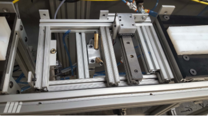
Above, a protective film application machine used in the manufacturing sector. The cutter head section of the machine uses the square rail and bearing to index the cutter. Image courtesy of Motion.
Caged vs. non-caged
Profile rail can also be specified with either caged or non-caged bearings. In caged deployment, each bearing is encased as a separate link in a self-lubricating polymer chain. This prevents the balls from rubbing against each other, enhancing the smooth and quiet operation, but it does so at the cost of speed, which is limited by the reliance on the polymer chain. Top speeds are up to 3 m/sec. with acceleration to 50 m/sec2—about the same as what you would get from rollers instead of balls.
Speed factors for round rail
Like profile rail, round rail consists of a shaft, a carriage containing the rolling elements and end caps (Figure 2). A key difference is that round rail is more subject to inaccuracies due to deflection or misalignment. This is addressed by using either end-supported or fully supported configurations and self-aligning bearings.
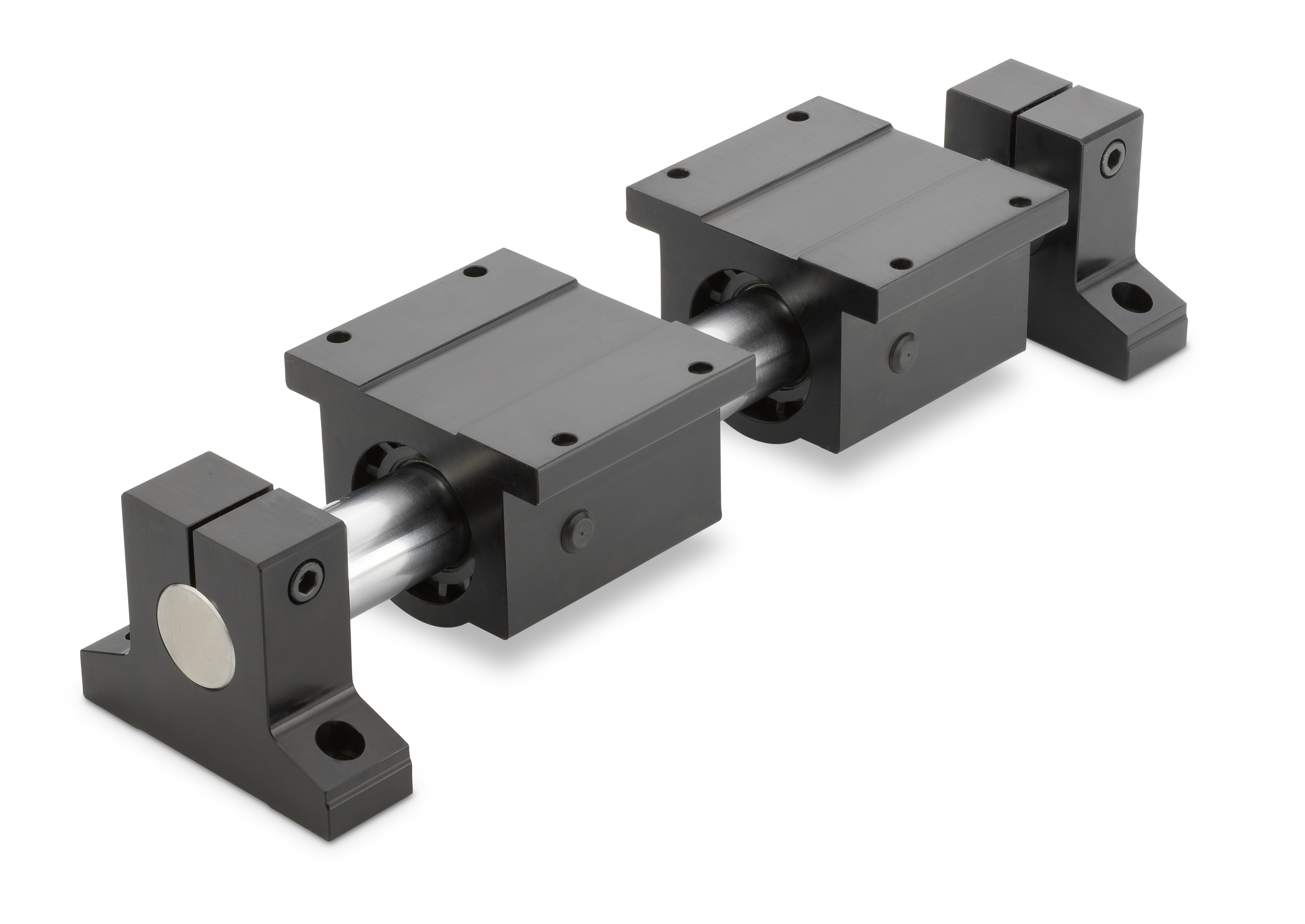
Figure 2. A round rail system consists of a shaft, a carriage and end caps.
Round rail systems are simpler and less expensive to produce than profile rail systems. Designers often specify them when cost control is top priority, and accuracy and high load handling are not. Speed is largely a function of whether they use standard Ball Bushings®, self-lubricating ball bearings or rollers.
Ball Bushings vs. rollers in round rails
Round rail Ball Bushing assemblies are limited in speed due to their recirculation system. Maximum speed is 3 m/sec with acceleration up to 50 m/sec2, making their speed comparable to profile rail using rollers or caged balls.
Round rail system rollers are convex and chain-driven (Figure 3) and can achieve much higher speeds. This roller assembly does not require an end cap, which gives rollers more freedom to recirculate at higher speeds. Travel speeds of up to 31 m/sec with acceleration up to 138 m/sec2 are possible with high load capacity comparable to a profile rail.
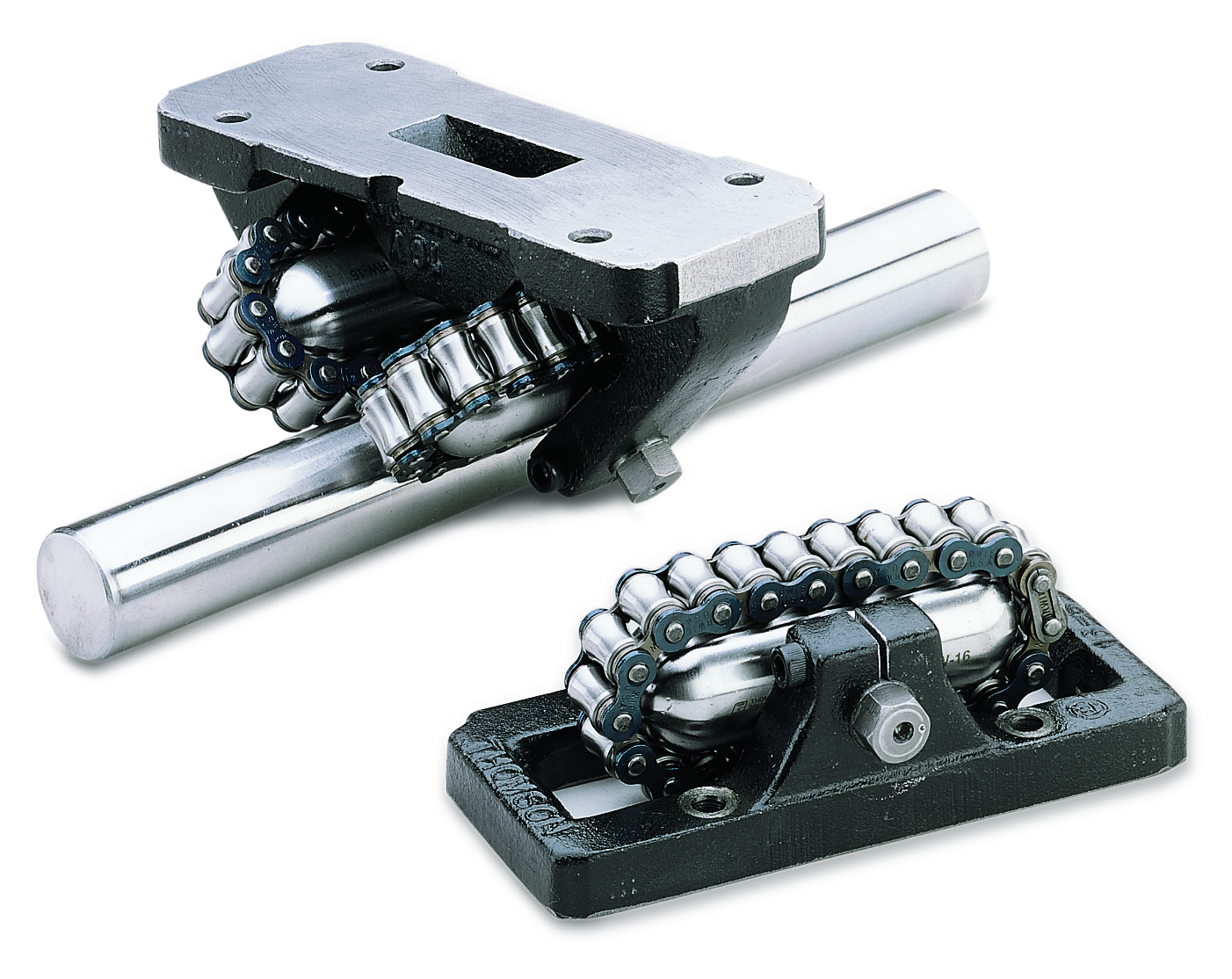
Figure 3. Thomson RoundWay® linear roller bearings provide smooth, accurate and high-speed operation in high-load, heavy-duty applications. Travel speeds can reach 31 m/sec with up to 138 m/sec2 acceleration.
Standard vs. self-lubricating bushings
Designers looking to achieve smooth operation amidst extremely harsh environmental conditions might deploy round rail systems with self-lubricating bushings. These require no maintenance and can be used at speeds up to 43 m/sec.
Meeting your need for speed
Of course, your final linear rail guide selection will depend on all motion parameters, such as load size, envelope and environmental factors. But when it comes to speed, the first question to answer is whether you will be designing your solution for use in a challenging environment. If the answer is yes, and speed is a priority, start by evaluating a round rail system with chain-driven, convex rollers. If speed is not your top priority, look at round rail systems with self-lubricating Ball Bushings.
If meeting challenging environmental conditions is not a top priority, but speed, high accuracy and load handling are, you should evaluate profile rail systems with ball bearings against your motion parameters. If you want that high accuracy and load handling along with the smoother operation, then look at a caged ball configuration, keeping in mind that you will lose any speed advantage from the profile ball recirculation technology.
If high load handling and accuracy are less important than initial cost savings of your chosen rail, and you are comfortable with speeds up to 3 m/sec, you will find many options among round rail systems using standard Ball Bushings.
Taking the time to consider speed-related factors that impact your applications will help ensure your loads reach their destinations on time.