

When manufacturing processes require high precision, high-speed repeatability and flexibility for applications such as CNC, robotics and material handling, production engineers often specify linear motion technologies. A basic linear motion system integrates a power component, such as a motor; a thrust mechanism, such as an actuator; and a guidance infrastructure, such as a rail. There are numerous subsystems within these categories, and understanding your options will help determine the ideal linear motion technology for your application.
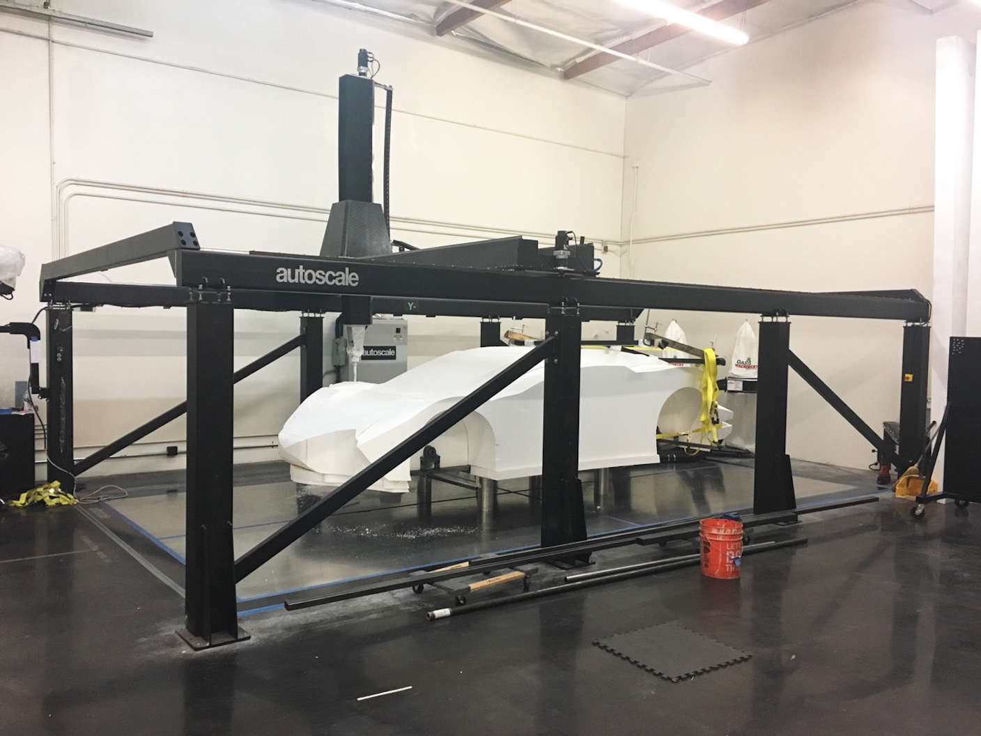
CNC and material handling applications require accurate and durable linear motion systems. (Images courtesy of Thomson Industries, Inc.)
Power components overview
The power components of the linear system include its motors, drives and controls. These convert electrical energy into mechanical energy and assist in positioning the device.
The mechanical energy can be rotary-to-linear or direct-to-linear motion. Rotary-to-linear drives will convert the rotary torque of a motor into axial travel through a gearhead/gearmotor or actuator connection. Electrical linear motors produce direct linear motion without rotary components. The motor driving the system can be controlled to provide the desired velocity, acceleration, torque and position to yield optimal performance.
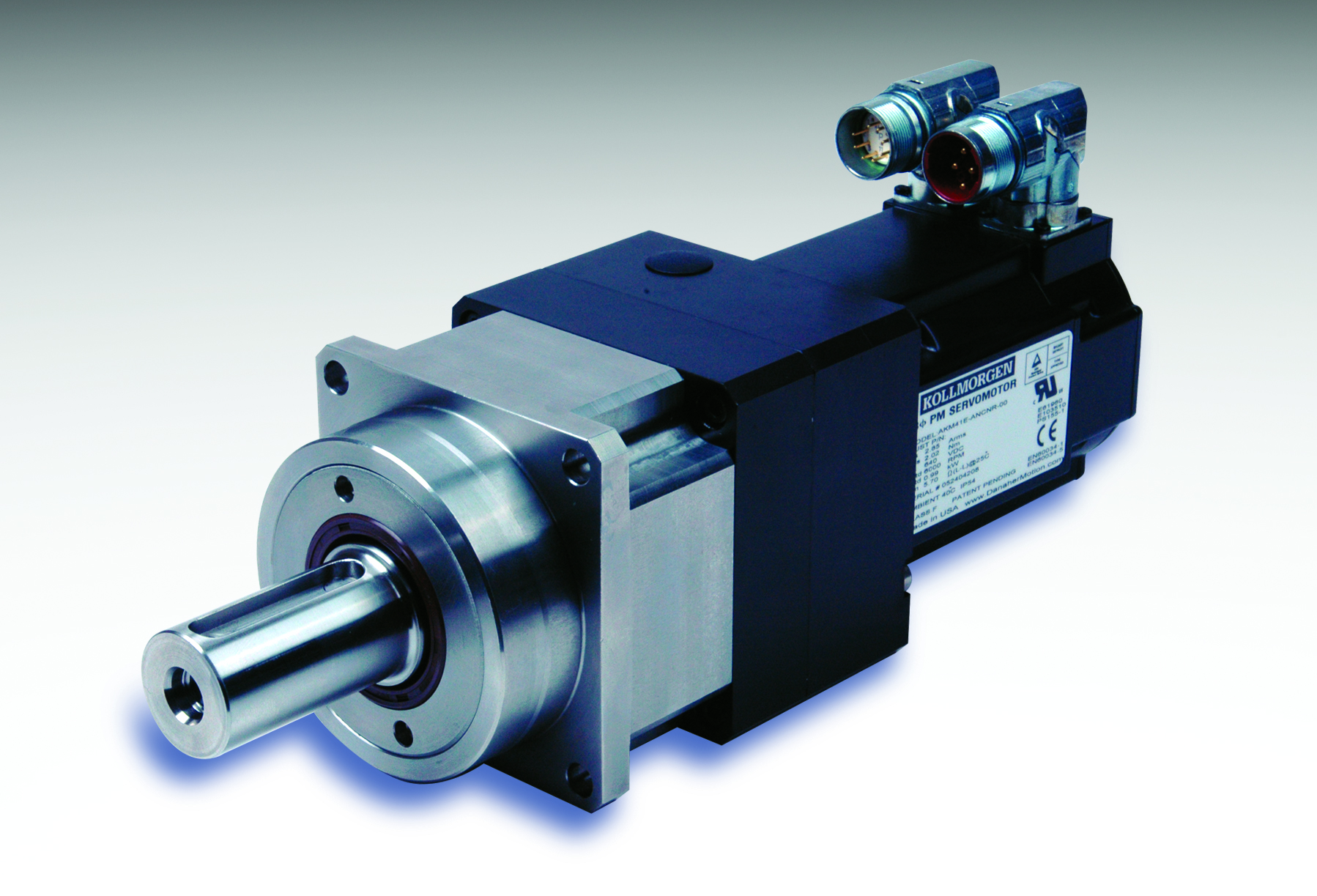
The Thomson Precision Line (ValueTrue) gearmotor offers smooth and precise operation with a high torque density. Its design offers performance, reliability, cost and maintenance advantages.
Drive options include servo motors, which enable the most accurate position control in multiple poles and axes; stepper motors, which provide accurate position management but for a limited range of positions; and variable speed drives, which can control speed only.
Achieving positioning accuracy is done by integrating controls, switches, sensors and optical encoders. A servo motor, for example, has so many poles that determining location at any point requires an encoder to generate pulses that indicate the exact position of the rotating shaft. Controllers use such information to calculate discrepancies between the actual system position and the desired location. Control systems such as programmable logic controllers (PLCs) can then be programmed to drive corrective actions based on reported anomalies or to drive complex operational sequences such as multi-axis movements. As power drive components become increasingly digitized, encoding functionality that conventionally required external devices can be integrated, reducing complexity and footprint.
Moving the load
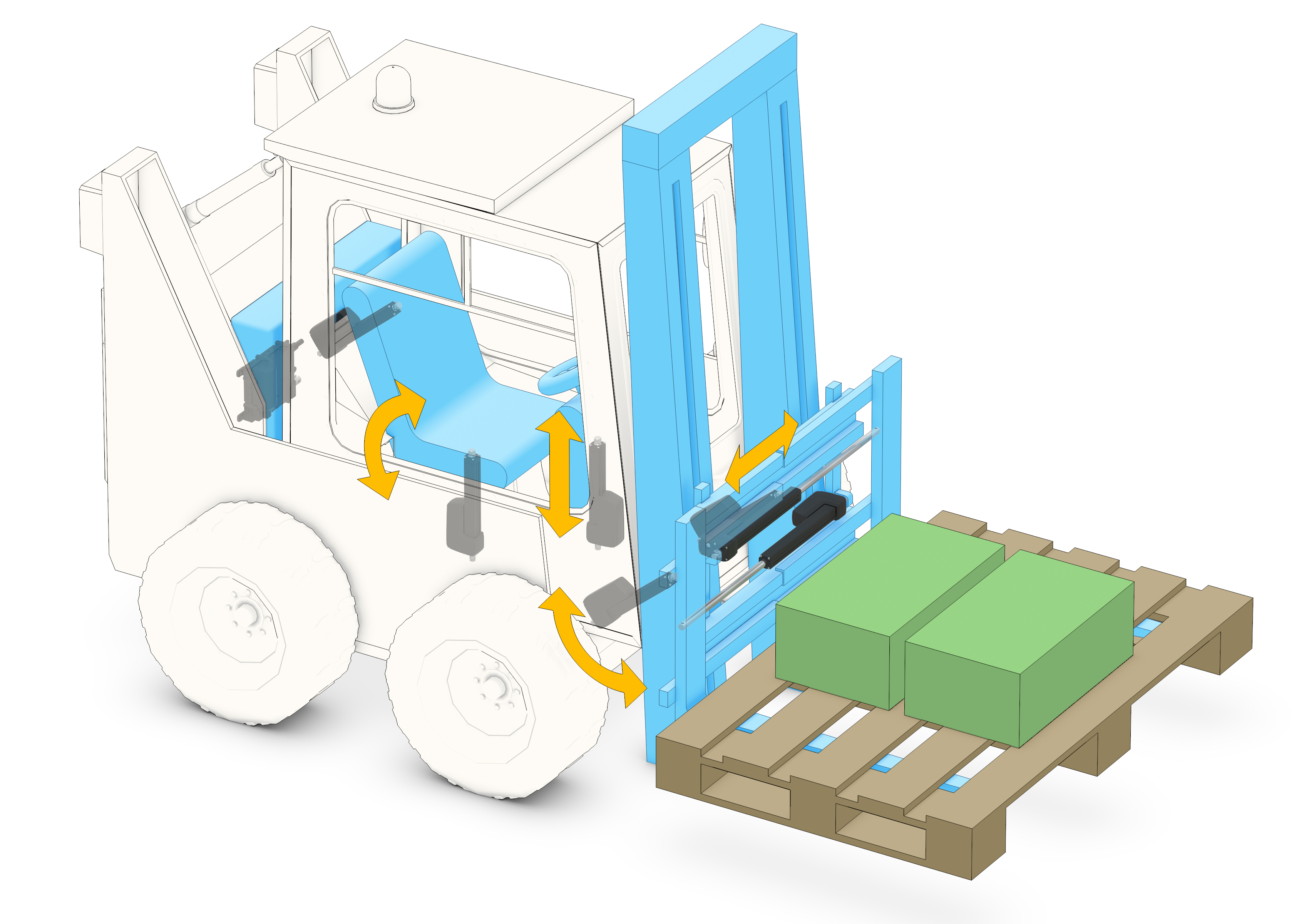
Powered by motors and drives and under the control of PLCs or other controllers, linear thrust mechanisms provide the physical contact that moves a load from one position to another. Because they “actuate” the load, they are often generally called actuators, but thrust mechanisms might also be ball screws, lifting jacks, cylinders, solenoids, belt drives or any other device that that convert rotary motion (torque) into linear thrust on one or more axes.
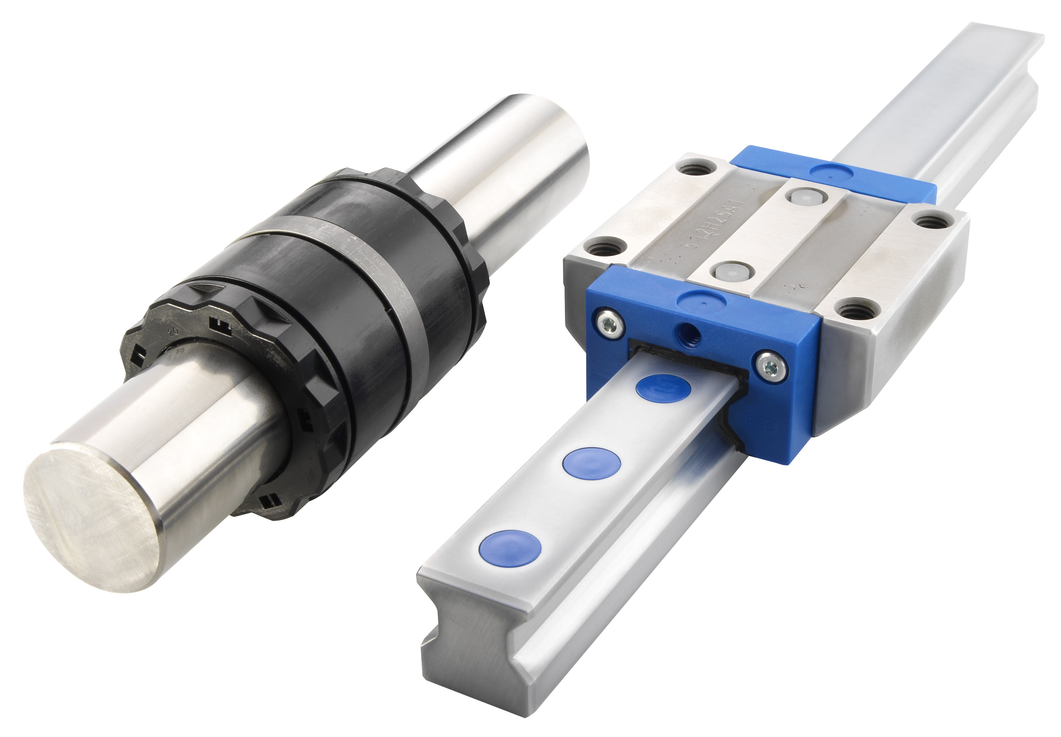
Thomson bearings and profile rails used in test and measurement equipment, robotics and pick & place equipment provide the length, durability and accuracy design engineers need for their systems.
The bearing blocks fasten to a carriage and may often be referred to as bearing housings, bushings or trucks. The carriage itself is also known as a saddle, platen or table. In a machining application, the carriage may be secured firmly to the part that is being machined or moved and may sometimes be moved by robotic arms. If a carriage is used, then multiple rail assemblies can be deployed for multiple axis movement. The rails also provide additional support for the carriage and bearing blocks.
To deliver the required accuracy, rails must be perfectly straight and smooth. Steel rails and shafting, which are used in guidance and support structures, are made to more exacting standards and tighter tolerances than plain bearings that are used in power transmission shafting.
Shaft supports hold up the rail or shaft and are fixed by fasteners to the bed. These are necessary to minimize shaft deflection that can jeopardize system accuracy. There are three main types of shaft support: continuous supports, which have the greatest rigidity and load-carrying capacity; intermittent supports, which are spaced along the rail; and end supports, which hold up each end of the shaft.
Linear bearings support lateral rather than rotary movement. They travel back and forth on the rails at a predetermined cycle rate. For round rails, they could be ball bushings or plain self-lubricating bearings that are enclosed and supported in some type of block/housing mounted to a bed.
Specifying linear motion components
The most important factors to consider when sizing, selecting, installing and operating a linear system are the loads and moments, speed, acceleration/deceleration, required accuracy, duty cycle, parallelism, rigidity and repeatability. Here are some factors to consider in relation to each.
- Load and moment -- The loads are classified as radial, reverse-radial, lateral, reverse-lateral, axial and reverse-axial. Moment forces are classified as pitch, yaw and roll. Analogous to an airplane, pitch would be whether the nose is up or down, yaw would be motion to the left or right, and roll would be when the wing tips are up or down. The guidance portion of the system handles all of the loads and moments with the exception of the axial and reverse-axial load, which are taken care of by the thrust mechanism.
- Speed -- Speed is the rate at which a moving object is able to move or operate, and is normally referred to as the top constant speed the object reaches. Increasing speed comes with higher power requirements, so one should carefully consider the entire motion profile for minimum power consumption
- Acceleration/deceleration -- Acceleration/deceleration refers to the rate at which objects change in velocity over time. Excessive acceleration/deceleration yields in unstable motion and excessive strain on guide components due to induced moment loads, all which can lead to less service life of the system.
- Required accuracy -- Accuracy is how closely the system moves compared to a commanded position. It is a function of many variables, including the accuracy grade of the components, installation practices and mounting accuracy of the machine base.
- Duty cycle -- Duty cycle is the amount of “on time” versus “total time,” or it can be defined as the number of reciprocating motions per minute. This is one of the most critical factors impacting the life of the system.
- Running parallelism -- Maintaining parallelism of the linear rails and shafts is critical to consistent performance and design life. When the table moves, rail parallelism will prevent binding in the bearings and overall inaccuracies in the system.
- Rigidity -- Rigidity is important because the system must be stiff or rigid enough to prevent deformation or unintentional movement. Undesirable deflections during operation can result in production errors. Preloading ball screws, fastening components properly, torqueing fasteners correctly, and having firm end supports on thrust mechanisms all contribute to improved rigidity.
- Repeatability -- A linear system’s repeatability relies on its components consistently moving from one point to another and back with minimal error. On servo systems, for example, sensors, limit switches and encoders provide feedback that can help control errors and positioning.
With so many factors to consider, the chances of mismatching motion control technologies to one’s applications are high. Linear component manufacturers provide automated tools that help compare options and manage tradeoffs. Thomson Industries, for example, offers online tools that help design engineers accurately size and select linear motion systems and other components. It provides an interactive series of questions, starting with a comprehensive analysis of motion control requirements, quickly leading to an ideal solution for the customer’s application.
The Thomson Linear MOTIONEERING sizing and selection tool offers designer engineers real-time adjustments, and intuitive product filtering and comparisons for component specifications in typically less than 15 minutes.
Whether you use an automated selection tool or your own calculation, adequate attention to selection of power components, thrust mechanisms, and guidance and support systems can help you maximize the precision and repeatability you get from your production operations. While proper selection provides the foundation for success, installation, operation and maintenance are the building blocks.
Installation, Operation and Maintenance Guidelines
Proper installation, operation and maintenance of linear components are essential to maximize the service life of a linear motion system. The following are general guidelines for linear thrust and guidance mechanisms.
Installation tips
- Mount the components on a clean, level and solid foundation. Mounting accuracy of linear systems usually will mimic that of the base or bed.
- Position the actuator or screw axis at center and parallel to the load as much as possible to prevent detrimental moments. Avoid side loading and cantilever mounting.
- Make sure the entire linear assembly is as rigidly mounted as practical.
- Using dial indicators, determine that all rails are level and parallel with each other.
- Ensure that the thrust mechanism will run back and forth freely during installation.
- Minimize spans between drive components. Short, straight connecting shafts are ideal for the system.
- Utilize additional bearing supports for drive shafts whenever possible.
- Use zero-backlash, flexible couplings and gearboxes.
- Incorporate limit switches and sensors into the system to control travel distances and positioning.
- When mounting profile rails, observe the datum line on the reference rail and place it against the datum plane.
Operating tips
- Avoid excessive compression loads (column loading) on thrust devices. Heavily loaded vertical applications and high-speed horizontal applications are prone to column loading.
- Do not exceed the limiting speeds of all linear components.
- Make sure brakes and anti-rotation devices are used to prevent unintentional back driving and effective stops.
- Make sure brakes and anti-rotation devices are used to prevent unintentional back driving and effective stops.
Maintenance tips
- Lock out, tag out and verify that the system is neutralized prior to any service work.
- Use protective bellows, boots, seals and covers whenever possible to prevent foreign materials from interfering with movement and causing wear.
- Properly torque all fasteners to the specified amount.
- Lubricate all steel surfaces with light machine oil.