

Niklas Sjöström from mechanical motion control manufacturer Thomson Industries explains the key factors.
By Niklas Sjöström
Product Line Manager, Systems Group
Thomson Industries, Inc.
www.thomsonlinear.com thomson@thomsonlinear.com
Over recent years, there has been an increase in demand from end users to increase the use of electric rod style actuators, and reduce the use of pneumatic actuation in factory automation equipment. Numerous factors are driving the conversion but most significant is the increasing need to achieve the following objectives:
- Improved machine performance and functionality, due to electromechanical actuators being capable of higher precision.
- Smaller footprint, because electromechanical actuators require only about a quarter of the space to deliver the same thrust.
- Greater energy utilization, because electromechanical actuators operate with a far greater energy efficiency and do not need air compressors running 24/7 to maintain pressure
- Reduced maintenance and total cost of ownership, because electromechanical actuators use fewer components, do not require compressors and do not have air leak issues.
Once the decision to replace pneumatic actuators with electromechanical actuators has been made, the next step is to select the right electromechanical actuator from among the many brands. While fundamental thrust specifications may be similar, there are significant differences in the areas of lifecycle performance, maintainability and environmental resistance.
Lifecycle performance
Generally speaking, the larger the diameter of the ball screw, the greater the thrust potential, but achieving this requires proper mating of the thrust bearing and all fixation points, including extension tube, the inner ball nut system, bearing housing and wiper housing. Otherwise, any increase in thrust would come at the expense of system life. A component that is too weak to handle its load will wear out much faster or even become damaged. Given two actuators, each fitted with a 16 mm ball screw and providing 750 Newtons of thrust, for example, one may have travel life of 2000 kilometers, while another could provide 8000 kilometers of travel. The difference is in how well the ball screw is mated to the other components and them to each other.
Moreover, due to larger ball screw diameters correlating also with cost and footprint, properly mating the ball screw and other components can reduce both. To meet an application requirement of 3200 Newtons of force, one vendor might utilize a ball screw with 20 mm diameter, while another vendor with properly mated components, might achieve the same thrust with a screw of only 12 mm diameter, thus being able to downsize without sacrificing performance.
Proper mating of ball screws and other components has the greatest impact on the life of the actuator, and this together with the carrier design has the greatest impact on precision and load capacity. One of the carrier’s main functions is to reduce free play in radial and lateral directions. Factors impacting this are the diameter of the carrier body, the contact surface area and the use of support legs.
A larger carrier body, (Fig. 1) can support larger external radial loads, by maximising surface contact area in a side load situation. The ability to side load electric actuators would raise performance, precision and compactness to a level that is not attainable with pneumatic or hydraulic actuation.
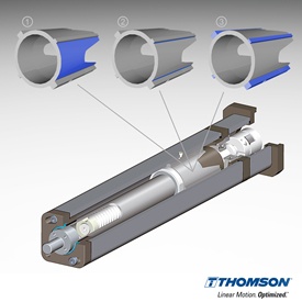
Fig. 1 shows the contact areas in thrust and side load conditions
Likewise, increased contact area in a pure thrust situation reduces play, providing support for lateral loads on the extension tube (Figure 2).
While maximising surface areas impacts radial and lateral load capacity; it does not necessarily impact stability. This is often addressed by interlocking elevated legs into grooved channels (③). These support legs also help reduce vibration, which can add noise and contribute to wear. Most designs use one or two such ridges, which remove some play but can generate clicking sounds as the system begins to wear over time. Using four legs instead of two, however, reduces wear and noise, providing more effective and more durable anti-rotational protection. The additional legs will also help ensure cling-free return motion, further reducing the amount of play in the system due to wear.
Additionally, curving these carrier legs outwards creates radial preload, which reduces play in the thrust tube and centers the carrier body and ball nut, eliminating the need to shim the carrier to the extrusion and compensating for wear over the life of the device. Keeping everything in alignment also reduces the frequency with which the system must be calibrated to achieve consistent idle torque.
While close tolerances are critical for wear and noise reduction, if there is no air gap at all, pressure can build when the actuator is running at high speed. This can cause overheating, contributing to lubrication problems and other durability issues. Thomson addressed this by making two of the male key features on the carrier legs lower than the remaining two. This provided just enough of gap to prevent pressure build-up. As seen in fig 1 two of the male key features on the carrier legs that is orthogonally situated are lower than the remaining two. This is what prevents the pressure build-up.
Maintainability
Ease of maintenance certainly affects lifecycle performance and contributes to immediate productivity benefits. Electromechanical actuators differ in their lubrication and motor handling. Most systems retract to expose parts for lubrication only partially, maybe 60 or 70 percent. Technicians remove the caps, locate the parts that need lubrication, add grease, and may need to repeat the process. A better approach, however, is to extend or retract the tube completely, revealing all components for maximum coverage. These few steps allow implementation of automated lubrication systems. In addition, using a lubrication nipple that eliminates the need to remove the cap simplifies maintainability.
Another key factor is installation time that is consumed in mating up the motor with the mechanical actuator. Traditionally mounting the motor in a parallel configuration can take 20-25 minutes. Once the motor is being mounted, a technician must use a variety of tools to adjust it for proper belt tension and aligning. This requires at least 12 steps. But if the actuator design comes with a pre-assembled parallel solution, the belt can be pre-tensioned during assembly, eliminating the need for the multistep tension adjustments, and enabling the motor to be bolted down and usable in only three steps. For inline mounting, the benefits of a pre-assembled solution are similar, although not as dramatic, reducing the number of steps from 7 to 3.
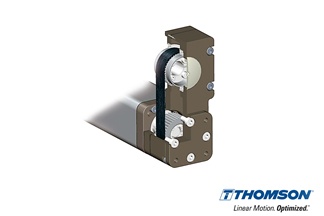
Fig. 2: Actuator design with a pre-assembled parallel solution.
Additionally, the use of a straddle-mount bearing strategy eliminates the risk of misalignment. Besides, it protects the motor shaft from impact by radial loads, which also reduces noise and further extends system life.
Environmental resistance
A very important point in which electromechanical actuators differ from each other is their ability to resist against harsh or environmental conditions and withstand frequent high pressure wash downs. This is basically a matter of the exterior profile design, material choice and sealing strategy.
Compared with grooved surfaces, an exterior profile with a smooth surface is cleaner, because it avoids accumulation of dust and fluids in grooves. This makes it more appropriate for harsh environments when frequent wash down is required. There could be one downside of a sleek exterior, though. If used in applications which require a sensor attachment, an additional plastic add-on might be necessary to attach the sensor.
Environmental resistance also depends on the material composition of the extension tube. Most systems use chrome steel, but stainless steel is a much better choice for harsh environments.
A key indicator of resistance to solids and liquids in the environment is the Ingress Protection (IP) Code of the National Electrical Manufacturer Association (NEMA) (Table 1). Achieving an IP rating of 65, for example, means that the system is completely dustproof and protected against low pressure water jets from any direction, as might be found in a food and beverage industry wash down operation. Only a few electric actuators available today meet this, but in corrosive environments it is critical. An IP rating of 54 provides some degree of dust protection and protection against splashed water, making it acceptable for some wash down applications but not if pressure is involved. An IP rating of 40, which is quite common among linear actuators, implies that there is no dust or liquid protection.
|
First digit: |
Second digit: |
|
|
0 |
No protection |
No protection |
|
1 |
Protected against solid objects over 50mm in diameter e.g. hands, large tools. |
Protected against vertically falling drops of water or condensation. |
|
2 |
Protected against solid objects over 12.5mm e.g. fingers, large tools and similar objects. |
Protected against falling drops of water, if the case is disposed up to 15 degrees from vertical. |
|
3 |
Protected against solid objects over 2.5mm in diameter e.g. thick wire, small tools. |
Protected against sprays of water from any direction, even if the case is disposed up to 60 degrees from vertical. |
|
4 |
Protected against solid objects over 1.0mm in diameter e.g. wires. |
Protected against splash water from any direction. |
|
5 |
Limited protection against dust ingress. |
Protected against low pressure water jets from any direction. Limited ingress permitted. |
|
6 |
Totally protected against dust ingress. |
Protected against high pressure water jets from any direction. Limited ingress permitted. |
|
7 |
N/A |
Protected against short periods of immersion in water. |
|
8 |
N/A |
Protected against long, durable periods of immersion in water. |
|
9k |
N/A |
Protected against close-range high pressure, high temperature spray down |
Table 1 NEMA IP Codes rating protection against solids and liquids
A higher IP rating is mainly related to a higher sealing strategy. In this case, every compartment is sealed, including motor mounts. All gaskets should also be sealed and extend all the way back to the motor, instead of stopping at the mounting plate.
Gearing up for the next generation of motion control
As the market drives demand for high productivity solutions, shorter changeover times, increasing reliability and greater energy savings, reduced maintenance and operating costs, more and more designers and end users are migrating to electromechanical actuation over pneumatic options. For machinery that requires sophisticated motion control, electromechanical actuators are pretty much the only alternative. But even in simpler linear motion applications, motion control designers and users are considering electric actuation based on less and easy maintenance, higher energy savings and cleaner operation.
Even greater benefits can be obtained with careful comparison among different brands of electric actuators. Always interpret ‘load carrying capability’ in the context of claimed system life and space requirements. There are very real trade-offs in these areas. Carrier design impacts precision, lateral and rotary load bearing capabilities, so pay close attention to the overall design used to secure the carrier in the channel, as well as to the shape and size of any guidance mechanisms used. Improved mechanisms and parts such as support legs and leg designs, which are curved for better gripping, will have a large positive impact to accuracy and wear. Considering the appropriate exterior profile, material choice and sealing strategy are important key factors for environmental resistance. Smoother profiles, stainless steel materials and higher IP ratings tend to offer the greatest protection.
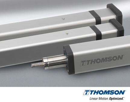
Title Image: Thomson PC Series electric actuators are designed to deliver superior performance while saving you time and money with easy product sizing and selection, quick and reliable installation, and reduced maintenance.
Visit www.thomsonlinear.com/pcseries for further information and to learn more about the benefits of converting from pneumatic to electric actuation, including a free energy savings calculator.