

More than eight million Americans and Canadians rely on canes or crutches, and most share one challenge: placing it conveniently out of the way when not in use. With the help of Thomson Industries, Inc., a team of engineering students from the University of Waterloo (located in Ontario, Canada) has prototyped a potential solution, using an electric linear actuator assembly that enables a crutch to automatically stand on its own.
There’s got to be a better way
After conducting research of challenges faced by disabled people, the Waterloo engineering team was amazed to see how disruptive crutches were to the daily activities of their users. “If you simply want a glass of water, you can’t just let go of your crutch; you need to find a way to support it,” said Connor McCallum, the team’s electrical design co-lead. “If the crutch falls, picking it back up can be difficult, especially for someone with a disability. And what do you do in a restaurant? A server might store it away for you, leaving you with no mobility options.”
These observations led the team to devote their mechanical and electronic engineering talents to developing a new crutch solution for their senior project. The students envisioned a crutch that could automatically stand on its own, freeing the user’s hands to perform routine activities more conveniently without losing immediate access to the support if they need it.
Bringing the vision to life
The Waterloo team roughed out a CAD design that outfitted the bottom of the crutch with small legs that would automatically extend or contract in tripod fashion after removing the crutch from beneath the armpit or letting go of the handle.
When extended, the legs would form a base about four inches wide, enough to support the crutch. For additional stability, the students envisioned a set of smaller legs that would brace the primary legs from the inside. They hypothesized that controlling leg operation would require a motor-driven rotating linear motion assembly of some sort and conducted an online vendor search, which led them to Thomson.
A consultative approach
On the Thomson website, the students quickly found their way to the stepper motor linear actuator section. These components combine a hybrid stepper motor and a precision lead screw in a compact envelope that they thought would work well at the end of the crutch. Using the Thomson online product selection tool, they entered expected motion parameters and saw a solution begin to take shape. To further refine their product selection, they followed a link to schedule a live virtual design consultation with a Thomson engineer.
“The students shared an early 3D model of their concept, which provided a solid basis for our discussion of exactly what they wanted to accomplish,” said Kyle Thompson, product innovation manager at Thomson. “We discussed stroke lengths, move distance, move time, speed and acceleration/deceleration options ̶ all guided by our online design tool.”
Marching the design forward
As the collaboration continued, the required motion assembly began to emerge. A stepper motor would rotate a threaded shaft along which the nut would ride. The nut would attach to the two collars, which would move along the core axis of the crutch. One collar would attach to the main outer legs (Figure 1, in red); the second collar would attach to the inner supporting legs (Figure 1, in green.) A single actuator would drive both collars.
To extend the legs, the motor would translate downward force through the nut to move both collars downward until the lower collar hits a hard stop, locking the inner legs into their bracing position. The upper collar then continues along its downward path, extending the primary legs outward to form the tripod that enables the standing. Reversing the motor rotation reverses this operation and retracts the legs.
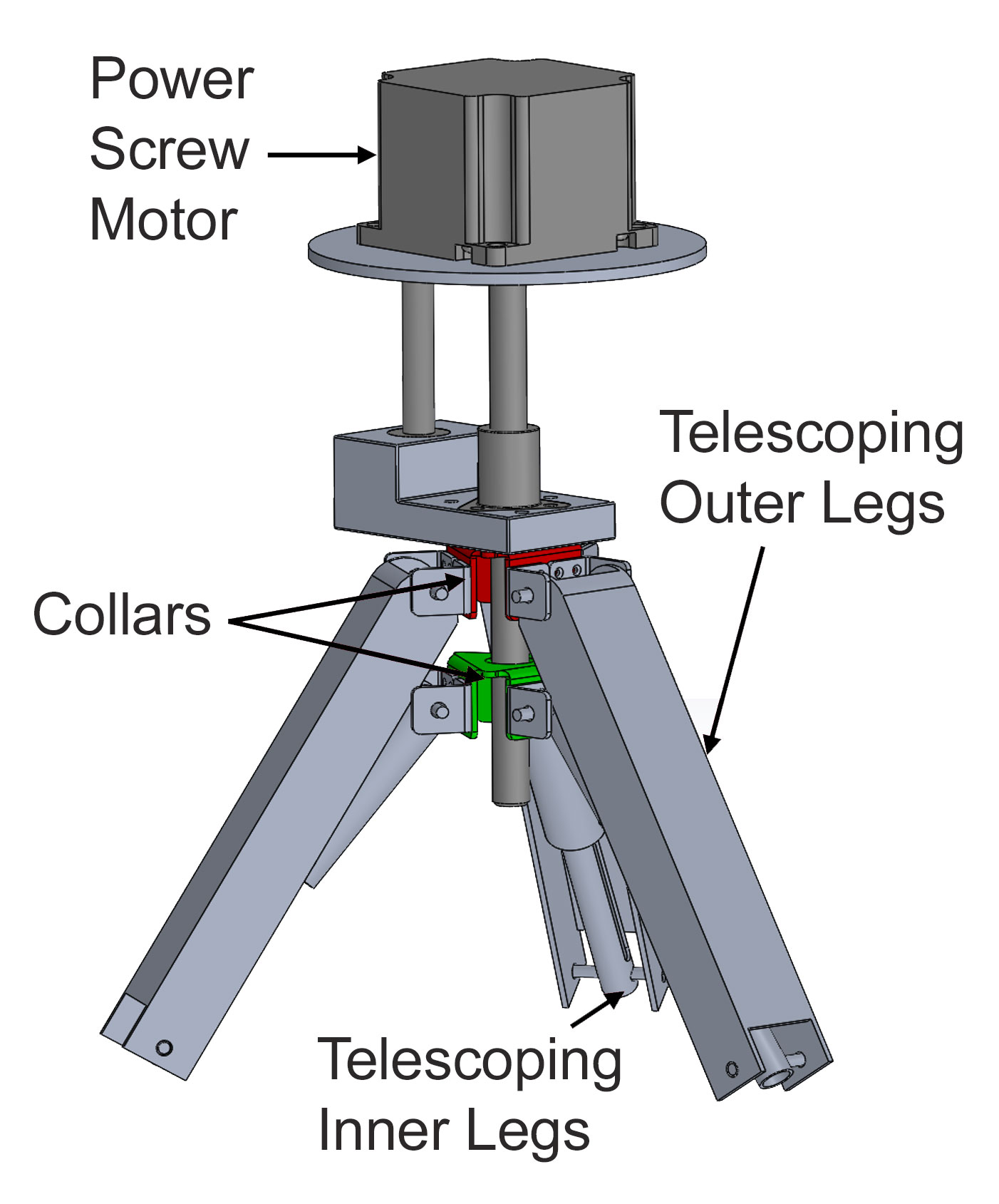
Figure 1. The crutch’s double-collared system features an upper collar (red) that guides the main telescoping legs and a lower collar (green) that guides the internal bracing legs.
Working with the tool and in collaboration with Thompson, the Waterloo team submitted its wish list of specifications. The actuator assembly had to support up to roughly 300 pounds of force; the legs had to open and close in less than a second with a travel distance of about two inches; it had to run on lightweight battery power; and ultra-high precision was not necessary.
The analysis concluded that a Thomson stepper motor linear actuator powered by a 12-volt battery would be right for the prototype. It could easily meet the force requirement; a NEMA 23 stepper motor would drive motion in less than a second; a six-inch-long lead screw would support more than the two-inch desired stroke; and a standard actuator would provide the precision needed. Although this satisfied the motion profile, Thompson advised the team that one more challenge needed attention.
Anti-rotational guidance
Because the nut must be free to move up and down the rotating screw, it might also rotate along with the screw, interrupting smooth operation. To prevent this, Thompson helped the team customize an L-shaped block that interfaced with the nut and rode with it along the main axis. The block was also fixed to a bushing guided by a shaft that was anchored to a plate just below the motor. (Figure 2)
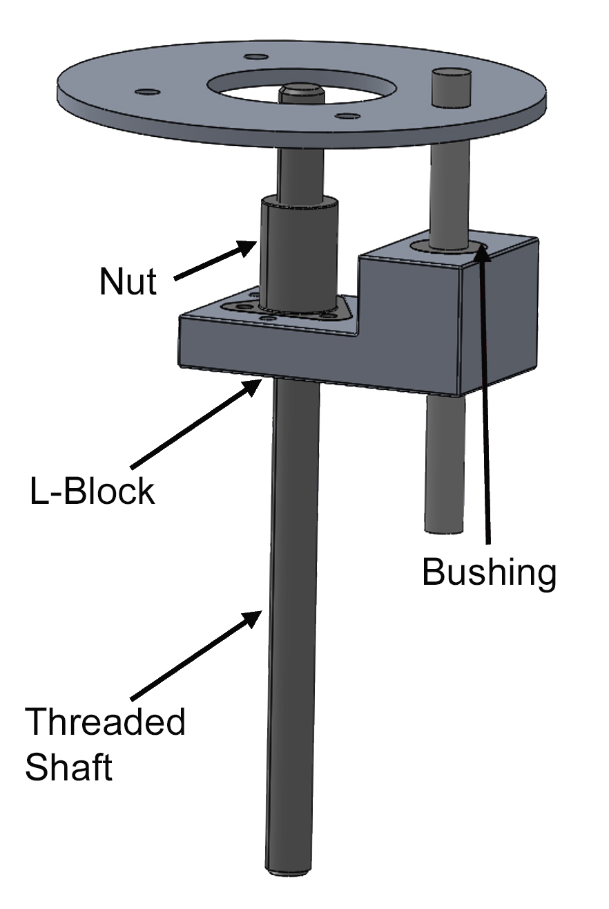
Figure 2. A retrofit, L-shaped block keeps the nut from spinning and causing friction.
“The Thomson virtual design session helped narrow our choices to determine exactly what product we needed to meet our design specifications,” said McCallum. “The online tool was easy to use and got us going, while Kyle was instrumental in helping us customize and optimize our motion. The way in which they helped us solve the anti-rotational issues is a great example of why it helps to have consultation with a motion design expert.”
When deployed, the crutch has a four-inch radius, and the inner supporting legs are at 40 degrees from the vertical. Deploying the outer legs at angles below 45 degrees prevents them from flipping inside out when they retract to their undeployed state. (Figure 3)

Figure 3. Self-standing crutch in standing position.
Expansion or contraction speed is 0.6 seconds with a travel distance of two inches, which is about 3.33 inches per second. The team intentionally restricted the top speed to prevent damage to the crutch prototype. The load-bearing components accommodate up to 300 pounds.
Smart operation
As illustrated in the purple sections of Figure 4, the team distributed the electronics evenly throughout the crutch frame to achieve optimal balance. A microprocessor in an electronics box near the top of the crutch frame receives analog signals from pressure sensors located in the armrest, handle and bottom, and sends them to the motor controller located in a box below it.
The motor controller would connect to the lead screw via wires fed through the hollow tubes of the crutch, although wires were exposed on the prototype. Limit switches were used to detect the position of the legs. The legs were controlled using pressure sensors on the crutch to determine if the crutch should be standing, if it is not in use, or if it should retract so that the user could walk with it.
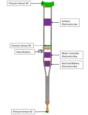
Figure 4. Self-standing crutch electrical controls.
Pressure sensors had to be compatible with natural human use. The bottom sensor, which signals whether the crutch is in contact with the ground, requires a relatively low threshold for activation. The armpit and hand sensors, on the other hand, trigger motion of the legs and require a slightly higher pressure threshold to prevent the legs from operating prematurely. A three-button control panel located just above the motor controller electronics box would enable the user to override the automatic controls.
Making good better
Once the team assembled the electrical and mechanical components, and integrated them within the crutch, it successfully stood up in its use case and met all desired requirements. The crutch automatically detected when it was left alone and responded accordingly. It was also able to toggle between manual and automatic modes.
Now that the Waterloo team has a working prototype in hand, they are reflecting on what might be done to improve the crutch’s operation. That would include making it more aesthetically appealing, using printed circuit boards, different materials and a smaller motor to save space and make it lighter, and feeding wires through hollow tubing instead of leaving them exposed. Wherever their vision takes them, they can be certain that the Thomson team will be standing right there beside them.