

Comparing electromechanical, hydraulic and pneumatic actuators
Travis Gilmer, Thomson Industries
Max Miller, Motion Industries
Actuators provide the push and pull of industrial automation. If something is moving on the plant floor, odds are good that an actuator is involved. Actuators vary according to the type of energy that drives them, with electromechanical, hydraulic, and pneumatic being the most common types. Each type has its advantages, and understanding the differences can help maintenance engineers reduce downtime and costs.

Maintenance benefits of electromechanical actuators, most notably those with integrated electronics, are being experienced in many markets, including on- and off-highway vehicles.
Actuator basics
The basics of determining the mechanical requirements for an actuator are similar regardless of energy type. Motion application designers first determine how much force is needed to move the load by calculating the weight of the moving parts combined with the friction force. The designer then determines the “Motion Profile” of the application. This consists of the amount of time the load will be moving – be it forward, reverse or dwell. The Motion Profile also includes the time it takes to accelerate and decelerate from zero speed to required speed and vice versa. In addition, it can contain any acceleration and deceleration times from one speed to another, if not starting or ending at zero speed. The total combined time of one profile is called a Cycle and can be measured in seconds, minutes, or hours.
By creating the Motion Profile, the designer can calculate the force needed to overcome inertia of the load as stated by Newton’s Second Law (Force = Mass x Acceleration.) The faster the required acceleration, the more force will be required to overcome the inertia, and that force will likely be higher than the weight and friction force initially used to select the actuator. To compensate for this, best practice is to apply a service factor or safety factor to the calculated force. The service factor protects the equipment and reduces wear; the safety factor protects the people around the equipment.
The weight and friction force adjusted by the appropriate service and safety factors define the work that needs to be done. The actuator is what does that work, and most industrial applications bring one of the three main actuator types – pneumatic, hydraulic or electric – to the task. All three types require electrical controls for start-stop to extend and to return. All three types are usually totally contained and protected from contamination, mount in similar fashion, but differ in cost, installation, energy efficiency, power density, intelligence and maintainability.
Electromechanical actuators
Electromechanical actuators are also called electric actuators or cylinders, and if they have an onboard microprocessor, they are known as “smart actuators.”
For higher cycle rates, an electromechanical actuator consists of a servo motor, gearing and ball screw driven rod. For intermittent duty cycles, usually 25 percent of actuator dynamic load capability, a DC or an AC motor replaces the servo, and both ball screw and lead screw options are available. Duty cycle is mathematically defined by the formula (On Time)/(On Time+Off Time) x 100=% Duty Cycle,which is limited by the heat generated inside the motor. Determining the duty cycle for a given load can be tricky. At some light loads, the actuator may approach 100% duty cycle or at least operate for multiple cycles before it must be turned off to cool the motor.
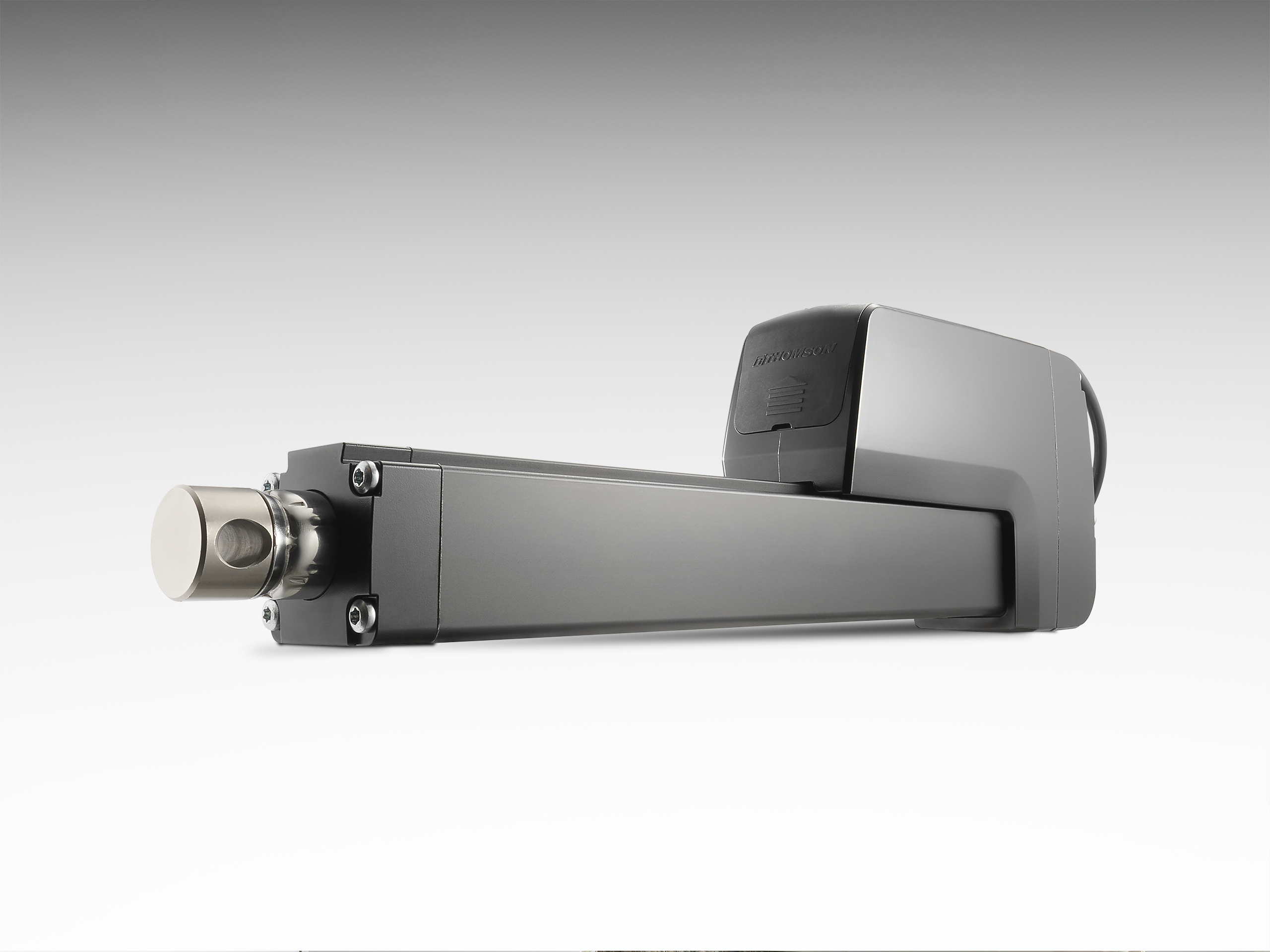
Self-contained, electromechanical actuators such as the Thomson Electrak® HD free machine designs of pumps, valves, hoses and associated fluids to service and replace.
The benefits of electromechanical actuators include lower operating cost due to higher efficiency. From a traditional maintenance perspective, this higher efficiency corresponds to fewer replacements and because they do not require air or hydraulic fluids for their power source, there are no leaks to contend with. A caveat is that with the expansion of IIoT and requirements for more flexibility from existing production lines, electromechanical actuators are starting to be embedded with microcontrollers. This adds a new dimension of operation along with a new dimension of maintenance capability.
Smart maintenance
With an onboard chip, electromechanical actuators can now be programmed to maintain constant speed under changing loads. Acceleration and deceleration can be controlled precisely. Positioning can be monitored and held without power if desired. Actuators can participate more easily and cost-effectively in plant networks promoting potential benefits for the maintenance function. This added level of intelligence is contributing to cleaner, more energy efficient operation. The fact that some previously external devices, like relays and limit switches, are now being replaced by internal electronics eliminates previously required effort to maintain the external devices and their related wiring.
An interconnected factory employing smart electromechanical actuators realizes countless benefits, including significant reductions in maintenance and downtime.
These additional benefits of the smart actuators will be supported by diagnostic information delivered across the network bus. Onboard electronics can, for example, track the number of cycles the actuator has run and provide operating temperature measurements and current consumption. Analysis of these factors could help determine whether increases in temperature or current consumption are related to abnormal wear on the system or to application demands. This can also benefit maintenance simply by shutting down a process to protect the application before overheating or current spikes damage the actuator. Prime examples of these advanced components can be found within the linear actuator families offered by Thomson Industries, Inc.
Hydraulic actuators
If power density is a priority, hydraulic actuators/cylinders may be the best choice. A two-inch bore hydraulic cylinder operating at 1,000 PSI can, for example, push more than 3,000 pounds. A hydraulic system requires a reservoir of oil, electric motor, pump, oil filter, relief valve, and directional control valve. The speed required and the size of the cylinder will determine the size of pump (GPM), and the size of the pump will determine the size of the electric motor, reservoir, filter, relief valve and directional control valve. The higher the speed required, the more the system will cost.
A hydraulic system converts kilowatts into flow and pressure. There are pressure losses in each component, including the conductors, hose and pipe. With proper design, these losses can be kept to a few percentage points. Cylinders are efficient until they begin to wear and leak around the piston. Pumps also are affected by wear and reflect this through internal leaks.
Efficiency of the system can vary as the type of hydraulic pump varies to meet the design criteria. Gear pumps are relatively inexpensive and, when new, are 85 to 90 percent efficient. Vane and piston pumps have efficiencies of 90 percent or higher. The most efficient system will use a pressure-compensated piston pump that will idle automatically, but maintain pressure when flow is not required. Operating the pump with an electric motor controlled by a variable frequency drive or a servo motor by a servo drive will greatly increase the overall efficiency of a hydraulic system. Proportional valves can be incorporated in the system to control acceleration/deceleration and be used to achieve mid stroke position. This comparison is for a single-axis actuator, but many hydraulic power units can provide flow to multiple cylinders, which require a more complex approach.
External leaks at pipe and hose fittings may occur over time due to vibration and other factors. The cylinder rod itself emits a film of oil out into the plant environment with every stroke. Internal leaks present an even greater maintenance challenge. Leaks inside the pump, pressure controls, directional valves and cylinder convert pressure and flow to heat or wasted energy. Any of these can lead to reduced actuator speed. Repairing leaks or replacing leaking actuators is an important part of the maintenance engineer’s job.
Pneumatic actuators
Pneumatic actuators are used primarily in simple applications requiring movement of relatively light loads back and forth between two positions. The position of the cylinder’s travel is controlled by the mechanical limits on the actuator or hard stops. Pneumatic actuators tend to be noisy as the actuator contacts the hard stop at each end of its limit of travel also decreasing their life with every impact. Most pneumatic applications do not require position control during travel.
If compressed air is already available in the plant, pneumatic actuators/cylinders are the least expensive to install and operate. If a constant, reliable air supply is not available, the cost of providing such could counter the other benefits of pneumatic actuators. Pneumatic actuators are also the least efficient in use of kilowatts, and maintenance of air leaks is a constant issue.
Toward a digital future
As more plant devices add intelligence, actuators will increasingly be called to duty on new applications. There will still be a place for pneumatic and hydraulic actuators in economical, or high-force applications. As newer technologies emerge combined with materials for both controls and mechanical drivers, the differences between the three types of actuation will be reduced. If ease of integration, precision, maintainability and lower cost of ownership are desired, the trend towards smart electromechanical actuators will continue to increase.