Technology Behind Electrak HD
Smart Onboard Electronics for Easier Control
Thomson’s Electrak Modular Control System (EMCS) is built into every HD actuator and serves as the foundation for the best onboard controls currently available on the market including, optional CANopen or SAE J1939 CAN bus control options.
Industry-leading Onboard Electronics
The Electrak Modular Control System is the culmination of decades of global design and application engineering in some of the toughest environments.
Electronic Monitoring Package – Standard on all Electrak HD Actuators
Safety comes first. Each HD electric linear actuator is equipped with the Electrak Monitoring Package which will constantly monitor critical parameters and take appropriate action as needed. Each unit will reset automatically when conditions return to normal allowing for operation to continue.
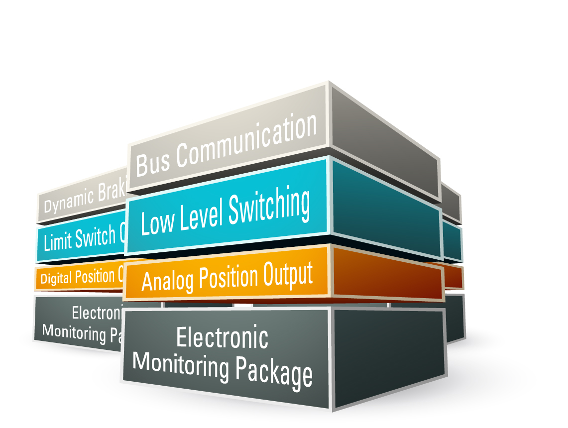
A Wide Range of Optional Control Features Within the Same Compact Envelope
Optional control functions can eliminate the need for external controls, saving design and installation time, as well as space and installed cost. A generous selection of control configurations can tailor HD to fit a great breadth of heavy-duty applications. The available control configurations are described on the next page and more details, including wiring diagrams for each option, begin on page 22 of the Electrak HD Brochure.
Electrak Monitoring Package Standard Features
Current Monitoring
A critical safety feature that shuts down the actuator on overload and eliminates the need for the traditional noisy, mechanical clutch.
Voltage and Temperature Monitoring
Continuous monitoring protects the actuator by preventing motion if outside normal ranges.
Temperature Compensation
Boosts productivity by enabling normal operation at lower temperatures without nuisance tripping.
Load Trip Point Calibration
Each Electrak HD actuator is individually calibrated at assembly to ensure a repeatable overload trip point.
Internal End-of-Stroke Limit Switches
Built in to each HD actuator, they ensure smooth, repeatable operation and protect both connected equipment and the actuator.
End-of-Stroke Dynamic Braking
Enable quick end of stroke stops putting less stress on the internal mechanical parts.
Optional Control Features
CANopen and SAE J1939 CAN Bus Control Options
Allow plug and play connectivity on your already established bus network.
Synchronization Control
Enables motion integration of two or more actuators to share a load, achieving optimal load distribution and control with a simple switch.
Mid Stroke Dynamic Braking
Standard with the low-level switching or the CAN bus options. Reduces coast, improving repeatability.
Low-Level Switching
Improves safety and simplifies design by using low current (&ls; 22 mA) signals. Also saves energy with an auto sleep feature.
Limit Switch Output
Confirms successful operation by indicating the actuator is fully extended or retracted.
Analog Position Output
A high quality potentiometer with essentially infinite resolution and low noise provides a voltage signal for position and direction feedback.
Digital Position Output
An encoder provides a single channel pulse train for position and speed feedback, which can be used to allow synchronization via customer control.
Programmable Limit Switches and Signal Follower
Allows for user-defined stroke limits and analog signal stroke control.
Control Option Combinations
- EXX = Electronic Monitoring Package only
- ELX = EXX + end-of-stroke indication output
- EXP = EXX + analog (potentiometer) position output
- EXD = EXX + digital position output
- ELP = ELX + analog (potentiometer) position output
- ELD = ELX + digital position output
- LXX = EXX + low-level signal motor switching
- LLX = EXX + LXX + end-of-stroke indication output
- LXP = EXX + LXX +analog (potentiometer) position output
- CNO = SAE J1939 CAN bus + open-loop speed control
- COO: Can Bus CANopen Control + Open Loop Speed Control
- SYN = LXX + Synchronization option
- LPS = EXX + LXX + Programmable Limit Switches + Signal Follower
Bus Communication – The Future of Actuator Control
Controlling an actuator over a network bus opens the door to breakthrough opportunities in machine design. More control, monitoring and feedback options can eliminate the need for separate controls. These options will also simplify design, diagnostic feedback and installation while reducing installed costs.
The built-in CAN bus option makes it possible to communicate with Electrak® HD electric linear actuators over a simple two-wire network.
CAN bus in Practice
Electrak HD uses CANopen and SAE J1939 CAN bus, well-known, mature bus standards widely used in the material handling, construction and agriculture industries. Up to 8 Electrak HD actuators can be connected to the same controller and to other CAN bus controls in the network.
Complex, real-time interactions between multiple actuators and related systems are now much simpler to monitor and control.
Application Examples
- Check position of doors and hatches and take action depending on the situation.
- Monitor the temperature, overload condition or voltage variations, then take action across the network as needed. Examples: start ventilation, reduce speed or stop an operation.
- Confirm when position or other criteria are met.
- Synchronize the motion of several actuators.
Benefits of CAN Bus Controls
- Better controllability – more complex and more precisely controlled motion.
- Improved safety – feedback in real-time with all operations verified.
- Shorter design cycles and installation time – CAN bus means minimal wiring, no extra control boxes and quick connection to existing networks.
- Greater flexibility – use the same actuator with minor program edits for multiple applications instead of designing for unique actuators and controls for every type of application.
- Reduced costs – all the above will lead to reduced design, component, installation, operation and maintenance costs.
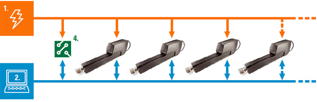
Control Architecture with and without CAN Bus
- A power (1) is distributed to each device.
- A main control (2) system communicates separately with an individual control (3) box connected to an actuator. Each instance may require individual design, configuration, wiring and installation.
- Other equipment (4) that needs to be controlled or integrated with the actuators requires separate controls with more design and configuration required.
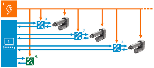
- A control system and actuators with CAN bus can communicate directly to each other. Adding additional, separately configured actuators is fast and easy. Only the power and a two-wire bus cable are needed to extend the network.
- Any other equipment with CAN bus can be connected to the bus and communicate directly.
- The result is a less complex system to design, better performance and controllability and reduced installation time and overall cost.