

Jonathan Wray
Global Product Line Manager
Linear Bearings & Guides
Thomson Industries, Inc.
Wood Dale, IL
www.thomsonlinear.com
Thomson@thomsonlinear.com
Introduction
Early in my career as a manufacturing engineer, I worked for a company that always designed automation equipment using the “good stuff.” We followed the rule that more expensive is better.
When it comes to profile rail, double-backed designs are generally more expensive than double-faced, so that is what we used. We seemed to be doing everything right - we mounted the rails to Blanchard ground plates and attached the carriages to precision-machined bars or plates. But when it came time to assemble the machine, the headaches would start.
Problems arose constantly. Once, the precision plate twisted because the welded table frame was not straight; another time, a small burr was the culprit. Even when everything went right, the alignment process was always a delicate balance. I couldn’t figure out why the good stuff was always so hard to install.
After doing some digging, I was able to find a presentation from an engineering professor that explained the pros and cons of double-backed versus double-faced profile rails, and the tradeoffs made in selecting profile rail versus round bearings. I discovered the reasons for our assembly difficulties and that we should have been using double-faced profile rails, or round bearings, for most of our automation systems.
This article explains how to choose between the main types of linear technologies, and how to design automation systems that deliver optimal performance using design requirements, rather than cost, as the primary consideration in selecting linear components.
Sidebar - Alignment & Physics 101 Refresher
Poor alignment is the leading cause of premature linear system failure. Often, engineers will encounter a failure and compensate by increasing the size of the bearings on the next system. As you read through this article, keep in mind that Lateral Force = Axial Force / tan(α). A system with ¼° of misalignment and an actuator capable of producing 500 lbf can generate a lateral force of nearly 115,000 lbf. We frequently see system failures with sheared bolts and cracked carriages. The payload itself is rarely capable of producing these failures. The culprit is almost always the force amplification caused by converging, diverging, and skewed alignment conditions.
Round and profile rails
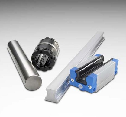
Round rails on left and profile rails on right

The self-aligning design of round rail ball bushing bearings allows them to be installed into imperfect systems

Let’s start by looking at the two main types of linear rails: round rails and profile or square rails. Round rails were used in the first linear guides and are still used frequently because they offer a number of advantages. Because the shaft is round, the ball bushings are free to rotate around its axis. This allows one rail to be installed at a slightly different elevation than the other. Also, bearing races on self-aligning ball bushings allow each linear bearing to rotate up to ½ degree in pitch and yaw to accommodate flatness or alignment errors. Pillow blocks are normally used to constrain the ball bushings, and rail supports typically provide enough flexibility to accommodate up to 25 mm parallelism error between the shafts. Round rail linear guides are thus self-aligning in all directions, so they are forgiving of poor parallelism and variations in rail height. In addition, the circular profile of round rail linear guides allows the shaft to be supported at the ends only. The axis of motion is established entirely by fixing the two ends of the shaft. Round rail linear guides can typically span gaps of 12 to 24 times the shaft diameter. Round rails mitigate the skidding of bearings as a result of the convex race having a minimal contact area with the ball. A typical light preload promotes smooth operation. Round rail wipers and seals have a simpler geometry with corresponding low drag and high reliability.

Profile rails used in X-Y stage assembly
Profile or square rail linear guides were originally designed to provide precision linear motion for machine tools. Profile rails are stiffer and more rigid than round rails but need straight continuous support so they cannot span gaps and they have much stricter requirements for flatness and parallelism than round rails. The principle advantage of profile rails is that they have an order of magnitude advantage in positioning accuracy compared to round rails. Profile rails can hold tolerances between 0.0002 inch and 0.001 inch over a length of 10 feet compared to 0.01 inch for round rails. Profile rail systems also offer higher rigidity and higher load life capacity than round rails. The ball conforming grooves on both the inner and outer races of profile rails increase load capacity beyond that of standard round rail guides. This geometry cradles the balls as they infinitesimally flatten under load, expanding the contact area between the races. The result is that profile bearing races are approximately 10 times stiffer than typical round rail systems.
Types of profile rails
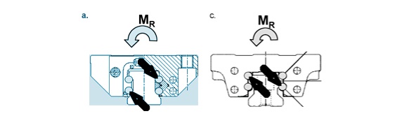
Double-backed rails, on the left, have a higher roll moment capacity than double-faced rollers, on the right.
There are several different types of profile rails, double-backed and double-faced being the most common. Double-backed profile rails utilize a back-to-back bearing arrangement that provides added rigidity. All else being equal, double-backed profile rails have a higher resistance to moment loads. This is because the vectors resisting the moment load are further from the center of rotation. This gives double-backed profile rails extremely high rigidity and accuracy. For applications that require extremely high location accuracy or moment resistance, double-backed profile rails are usually the optimal choice. However, the rigidity of the double-backed design also decreases the allowable installation tolerances, increasing surface preparation costs. Double-backed designs are unable to tolerate even minor misalignment so mounting surface preparation and proper installation are critical for proper operation and long life. If the mounting surface is not prepared properly, the guide will run rough and need to be replaced more frequently than normal. Small flatness errors in mounting surfaces can reduce bearing life by up to 50%. More severe alignment issues can result in immediate failures. Typical applications include machine tools, semiconductor manufacturing, circuit board assembly, and high accuracy machine axis applications.
Double-faced ball track bearing arrangements, on the other hand, utilize a 45 degree, face-to-face bearing arrangement to provide equal load carrying capacity in all directions. Double-faced profiles have a lower resistance to moment loads because the vectors resisting the moment load are closer to the center of rotation. The primary advantage of the double-faced configuration is that the rails are much more tolerant of mounting surface inaccuracies. This enables machine builders to reduce system costs by not having to prepare mounting surfaces for ultra-high precision. Mounting surface preparation and installation are still important to providing long life, but double-faced designs tend to be more forgiving. For applications that do not require extremely high location accuracy or moment resistance, double-faced profile rails are often the optimal choice. Double-faced profile rails also tend to have a lower initial cost. Typical applications include factory automation, packaging, material transfer, medical sample handling, and moderate accuracy machine axis applications.
Roller profile rails provide an even higher level of rigidity than double-backed ball profile rails by using roller bearings instead. Roller profile rails use the equivalent of a back-to-back bearing arrangement, complemented by special rollers that are crowned to prevent roller edge loading when misalignment is present. The result is lower elastic deformation as the load increases compared to a ball carriage or face-to-face bearing arrangement. Roller guides have a higher load capacity than profile rails with ball bearings as a result of the increased contacting surface across the length of the roller, due to the ball’s single point of contact versus a roller’s line contact area. This results in a substantially higher load carrying capacity and lower wear with minimum rolling friction. The cost of this increased precision and rigidity is even less tolerance for installation variance than double-backed ball profile rails.
Specifying a linear motion system
When specifying a linear motion system, one of the primary factors to consider is the amount of precision that is required in the application. Applications that require a high degree of precision and rigidity will often require double-backed profile rail linear guides. But these high precision linear motion components should be used only where needed because they are not only more expensive but, even more important, because they require a higher degree of preparation of the mounting surfaces in order to ensure a trouble-free assembly process and free movement during operation. If you are simply transferring something, perhaps moving a package from one station to the next, positioning to within a quarter of an inch may be all that is required. One the other hand, when you are moving a cutting tool whose position will directly impact the accuracy of the finished piece, then its location may need to be held to within three or four decimal places. This is the type of application that double-backed profile rail linear guides were designed for.
When double-backed profile rails are used, a perfectly flat precision ground mounting surface is needed because the rails will not flex to compensate for inaccuracies in the mounting surface. Misalignment or other inaccuracies in the mounting surface can cause several problems. The most obvious is when the carriage does not move freely over the length of the rails. In my experience, the best way to test the mounting surfaces is simply to attach the carriage to the rails and move it back and forth by hand along the complete length of the rail to make sure it runs freely. The carriage should move freely the entire length of the rail without any tight spots or binding. Motors and actuators can often push past tight spots, concealing the misalignment. Larger profiles or those with high preloads can be difficult to move by hand, but it is still good to use a force gauge or some other measurement of input force to detect issues.
The best way to achieve a perfect mounting surface is to use a Blanchard surface grinder to finish the mounting plate. The rails are then mounted to the plate and the plate is mounted to the machine base. One common rail alignment method is to mount one rail on a qualified surface against one qualified reference edge and float the second rail into place while moving the carriages. Two other alignment methods, in order of increasing complexity and accuracy, are to establish relative position of the rails by using gauge blocks, reference edges or a positioning laser. If the mounting surface is found wanting during the installation process, an alternative is to shim the rails to provide adjustment during the installation process. Shims run the risk of causing other alignment issues, so they should only be used as a last resort. It should also be mentioned that roller profile rail linear guides are an option that provides even higher rigidity and load capacity so they naturally have even tighter requirements in terms of the accuracy of the mounting surfaces.
Round rail linear guides offer the advantage of even easier installation than double-faced profile rail linear guides because they can accommodate torsional misalignment caused by inaccuracies in carriage or base machining or machine deflection with little increase in stress to the bearing components. These bearings allow for smooth travel when mounted to wide tolerance prepared surfaces. Round rail products can run smoothly when mounted to surfaces having a flatness error of more than 150 um per meter. Applications involving mounting bearings to welded tubular frames or even direct to concrete factory floors can be accomplished using round rail products. Of course, the ease of installation of round rail linear guides is offset by approximately an order of magnitude increase in the best achievable accuracies.
Real world applications
Next, let’s look at how these principles affect real world applications.
We recently experienced product failures with a customer who had just released a new machine generation, where the entire machine’s round linear bearings were replaced with double backed profile rail. The machine contained a large hydraulic ram that moved a heavy sled assembly. The failure mode involved the machine shearing the rail mounting bolts which then led to a catastrophic failure of the rails and carriages. Some machines operated fine, while others would fail after only a few cycles. The failures were caused by misalignment of the large hydraulic ram to the rails. They had never experienced problems with past designs because the round bearings were able to adjust to the misalignment. Our recommendation was to use meticulous care in aligning the system, and return to using round bearings in the next design update.
In another example, the mounting plate was raw, un-machined angle iron welded to the machine frame. In this application our recommendation was to first weld the angle iron and, after welding, grind the mounting surfaces. This approach worked well with double-backed profile bearings. On a side note, since accuracy was not critical in this application it would have been possible to use self-aligning round bearings with end supported rails mounted directly to the machine frame. This would have eliminated the need for the mounting plate all together.
The previous examples highlight the headaches caused by using high precision rails in designs that do not require the tight tolerances. We also see mistakes that go the other direction. Since double faced profile rail is usually less expensive than double backed, many machine builders make the swap to save costs. In applications where the precision is needed, switching to double faced profile rail from double backed or switching to linear bearings from profile rail, can be disastrous.
Conclusion
There are a large number of different linear bearing applications with many different loading and precision requirements. Developing a successful linear bearing application requires an understanding of the characteristics of the application and selection of a linear bearing and installation method that is a good fit to the application. The design engineer should consider the different characteristics of each type of linear guide and select the technology that provides the level of accuracy, installation requirements and cost that best fit the application.